15
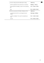
The reheater is controlled by the WTU with a 0-10V signal. Therefore, terminal 9
(-) of the CBA must be connected to terminal 11 (GND) of the WTU and terminal
10 (+) of the CBA to terminal 10 (0-10V) of the WTU.
When connecting the CBA reheater, the temperature sensor supplied with it must also
be connected to the WTU controller. The temperature sensor must be connected
directly to Analog Input 4 (AI4/contact 35) and Analog Earth (AGND/contact 33) of
the controller. The temperature sensor (supply air temperature sensor) connected to
AI4 must first be disconnected from AI4. The AGND already connected on the
controller should remain, the new sensor should be connected to the free AGND
(contact 33).
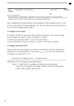
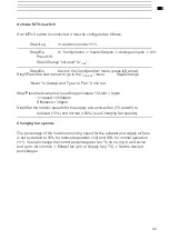
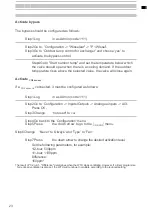
After connecting the CBA reheater, it must be configured in the controller (see
page 22).
Connecting to Building Management System (GBS/BMS)
The WTU can communicate with a Building Management System according to a
MOD-bus or BAC-net protocol. For this, a TCP/IP or RS485 cable must be laid
between the WTU and the Building Management System.
For the most up-to-date bus list see www.orcon.nl/BMS
Summary of Contents for WTU-1000-EC-E
Page 2: ...2...
Page 6: ...6 carried out...
Page 16: ...16 Note The connections shown in a box are optional Electrical Connections WTU EC E IE TA...
Page 41: ...40 Notes...


