background image


CONTROLS 


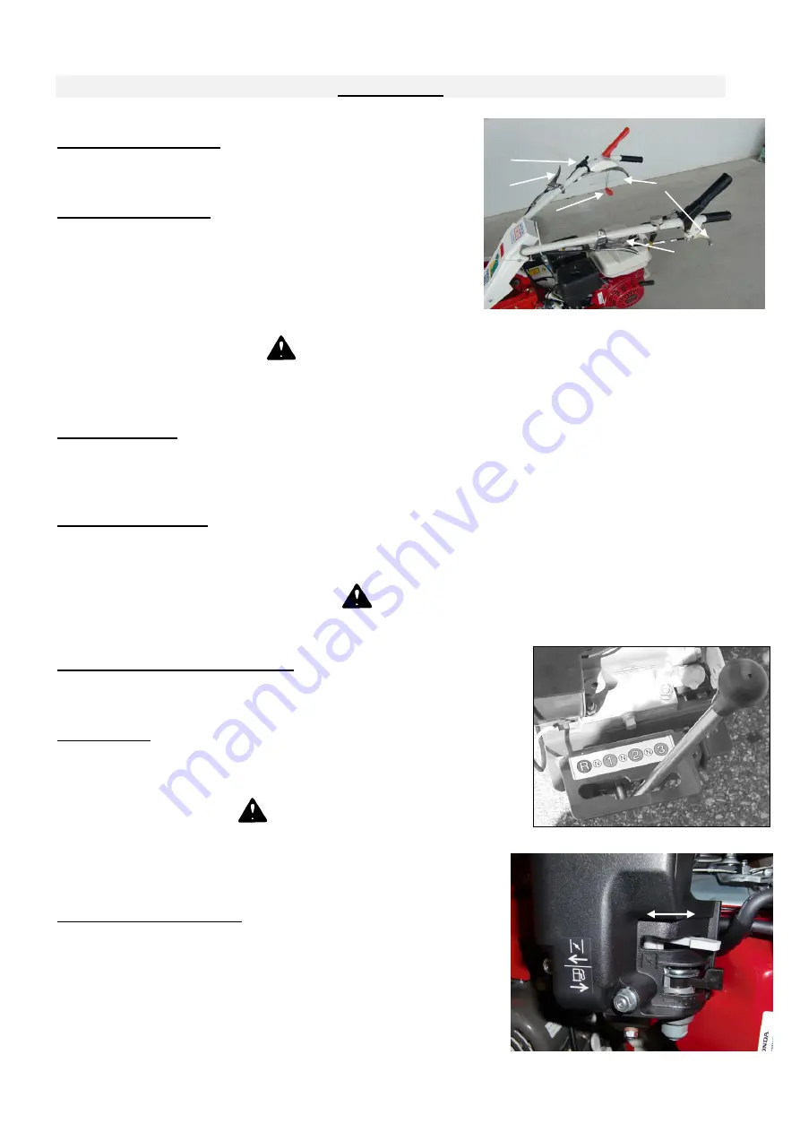
DRIVING CLUTCH LEVER 

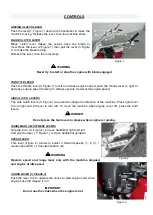
Push the lever(1, Figure 1) down to the handlebar to make the 
machine moving. Release the lever, then the machine stops. 

BLADE CLUTCH LEVER 

Blade  clutch  lever  makes  the  engine  drive  the  blade  to 
mow.Press  the  lever  (2,Figure  1)  then  pull  the  lever  (3,Figure 
1) to make the blade turning. 
Release the lever, then the rotor stops. 


WARNING


Never try to start or stop the engine with blade engaged 


THROTTLE LEVER 

Push the throttle lever(4, Figure 1) to left to increase engine speed, push the throttle lever to right to 
decrease engine speed to idle rpm. Always operate mower at full engine speed. 


SIDE CLUTCH  LEVERS 

The side clutch levers (5, Figure 1) are used to change the direction of the machine. Press right lever 
to  turn  right  and  left  lever  to  turn  left.  To  move  the  machine  when  engine  is  cut  off,  press  the  both 
levers. 


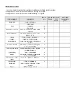
DANGER


Do not press the two levers in slopes when engine is running.


HANDLEBAR ADJUSTMENT LEVERS 

Grip the lever ( 6, Figure1) to move handelbar right and left. 
And grip the lever ( 7, Figure 1) to move handlebar up/dpwn. 

SPEED LEVER 

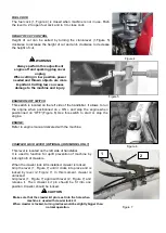
This  lever  (Figure  2)  allows  to  select  3  forward  speeds  (1,  2,  3),  1 
reverse speed (R) or 3 neutral location (N). 


WARNING


Operate  speed  and  range  lever  only  with  the  machine  stopped 
and engine at idle speed. 
 

CHOKE LEVER 

(1,


F

IGURE 

3)


Push the lever to 2 to operate the choke to start engine cold, when 
engine has start release it to 3. 


IMPORTANT 

Do not use the choke when the engine is hot 


Figure 2 


Figure 3 


Figure 3 


Figure 1                        

Summary of Contents for HR662

Page 1: ...alk behind flail mower Read this instruction manual carefully before any use of the machine keep it as a reference For any question about this manual please report to your OREC dealer or to the distri...

Page 2: ...DEL SERIAL NUMBER refer to the pictures herein Always mention these informations to your dealer in order to obtain the right parts Concerned about constant progress OREC keeps the right to modify the...

Page 3: ...NS 26 EC CONFORMITY DECLARATION 27 MEASUREMENT OF VIBRATIONS 27 EC CONFORMITY DECLARATION 28 MEASUREMENT OF VIBRATIONS 28 LIMITED WARRANTY 29 NOTES 29 SPECIFICATIONS Model HR662 672 HRC662 672 HR802 8...

Page 4: ...que chart Protect the grease nipples by coating them with grease and lubricate the machine Check that the machine can work properly CHECKS ON DELIVERY Show the user how to perform the adjustments Expl...

Page 5: ...en lifting or lowering the machine When stopping the work stop the engine and remove the sparking plug ignition cover before leaving the mower Engage all the safety equipments Move the controls only w...

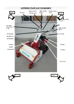
Page 6: ...lever Side clutch lever Handlebar adjustment UP DOWN Cutting height adjustment Front Driving clutch lever Left Right Rear Throttle Air filter Starter Fuel cock Blade clutch locking lever Fuel tank Han...

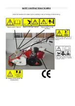
Page 7: ...ge or when missing Read owner s manual Beware of thrown objects Keep away from the machine Unplug the spark plug wire before perform maintenance read owner s manual Read owner s manual to be aware of...

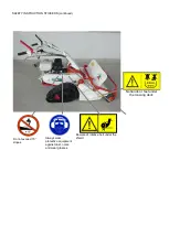
Page 8: ...Y INSTRUCTION STICKERS continued No hands or feet under the mowing deck Do not exceed 15 slopes Always wear protective equipment against dust noise and wear glasses Beware of rotative belt under the s...

Page 9: ...utch levers 5 Figure 1 are used to change the direction of the machine Press right lever to turn right and left lever to turn left To move the machine when engine is cut off press the both levers DANG...

Page 10: ...when positionned on OFF Figure 6 Use this switch to start or stop the engine ENGINE Refer to engine manual delivered with the machine CRAWLER LOCK LEVER OPTIONAL HRC MODEL ONLY This lever is located...

Page 11: ...that nobody or no object stands near the machine when at work They could be hit by the moving parts Nobody must stand on the machine except the driver Never put your hands under moving parts STARTING...

Page 12: ...machine on slopes Stop it on a level and flat surface STORING THE MACHINE Thoroughly clean the machine Use touch up paint to prevent rust Check for worn and damage parts install new parts as required...

Page 13: ...ome problems Ask your distributor the name of your dealer DAILY MAINTENANCE BEFORE START MOWING Transmission oil level check by the gauge 1 Figure 9 Oil level should appear in the hole Gear Oil SAE90...

Page 14: ...SAE 10W30 or API SL class Engine oil quantity 1 10L HR662 672 802 812 HRC662 802 1 28L HRC672 HRC812 Remove oil drain plug 2 Figure13 in case of changing oil Engine oil replacement First 20 hours Late...

Page 15: ...NLGI N 2 Grease the differents points G Figures 16 17 with light oil WIRES GAP Transmission wires If the machine does not stops when the drive clutch lever is released adjust the tension wire as follo...

Page 16: ...lade brake works correctly when adjusting blade wire control Direction wires If the wheel is not free HR662 802 or not locked HRC662 672 802 812 with side clutch lever engaged adjut as follows Uscrew...

Page 17: ...ft to the flails Stop engine and disconnect sparking cover Unscrew the 2 bolts of the shield to reach the belt Push the belt with a finger on F Figure 23 the belt must move from 3 to 5 mm If the belt...

Page 18: ...belt tension Check crawler tension every 50 hours of use 1 Secure the machine on four stands 2 Unscrew the nut A Figure 26 3 Turn the screw clockwise to increase the crawler tension and counter clockw...

Page 19: ...ble materials Drive clutch lever check machine do not move when lever is on N Brake Check efficiency of the brake Chassis Check for rust and cracks Safety stickers Check they are in place and in good...

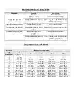
Page 20: ...ing clutch lever TIGHTENING TORQUES Nm Diameter of screw mm Mark on the screw head 4 7 8 9 11 3 0 3 0 5 4 0 8 1 0 5 2 5 3 4 5 4 6 4 6 4 7 4 6 4 7 4 8 8 9 8 6 4 9 6 9 9 8 11 8 11 8 13 7 11 8 13 7 14 7...

Page 21: ...assessment 2006 42 EC Annex VIII Measured acoustic power level 101 8 dB A Granted acoustic power level 102 3 dB A Conformity assessment 2000 14 EC Annex V Acoustic pressure level at operator s ears 8...

Page 22: ...assessment 2006 42 EC Annex VIII Measured acoustic power level 101 8 dB A Granted acoustic power level 102 3 dB A Conformity assessment 2000 14 EC Annex V Acoustic pressure level at operator s ears 89...

Page 23: ...ty assessment 2006 42 EC Annex VIII Measured acoustic power level 101 8 dB A Granted acoustic power level 102 3 dB A Conformity assessment 2000 14 EC Annex V Acoustic pressure level at operator s ears...

Page 24: ...assessment 2006 42 EC Annex VIII Measured acoustic power level 101 8 dB A Granted acoustic power level 102 3 dB A Conformity assessment 2000 14 EC Annex V Acoustic pressure level at operator s ears 89...

Page 25: ...assessment 2006 42 EC Annex VIII Measured acoustic power level 103 85 dB A Granted acoustic power level 105 dB A Conformity assessment 2000 14 EC Annex V Acoustic pressure level at operator s ears 91...

Page 26: ...30 UE Conformity assessment 2006 42 EC Annex VIII Measured acoustic power level 103 85 dB A Granted acoustic power level 105 dB A Conformity assessment 2000 14 EC Annex VIII Acoustic pressure level a...

Page 27: ...assessment 2006 42 EC Annex VIII Measured acoustic power level 103 85 dB A Granted acoustic power level 105 dB A Conformity assessment 2000 14 EC Annex V Acoustic pressure level at operator s ears 91...

Page 28: ...assessment 2006 42 EC Annex VIII Measured acoustic power level 103 85 dB A Granted acoustic power level 105 dB A Conformity assessment 2000 14 EC Annex V Acoustic pressure level at operator s ears 91...

Page 29: ...cted repaired or replaced The part s must be returned with freight prepaid and must be accompanied with a proof of the purchase The part s must be packed with the greatest of care to ensure their prot...

Reviews: