background image

12

GB

HOW TO CHECK REMOTE

TEMPERATURE

Once batteries are installed into the remote Thermo Sensor, it will
start to transmit temperature data at an approximately 40-second
intervals. Such data transmission is indicated by the blinking LED
on the remote Thermo Sensor.  Upon successful reception of the
remote thermo signals the data received will be automatically
displayed and updated at a 40-second intervals.

To  toggle between indoor and remote temperature display, press
[IN/OUT  TEMP].

If no signals are received, blank “—-“ will be displayed.  Press and
hold  [IN/OUT  TEMP]  for 2 seconds to activate search for the
remote thermo signal from the sensor. (Note: during this searching
period, reception of clock radio signal will be suspended)

If that fails, check if the remote thermo sensor is still in place.  Try
repositioning the units as they may be having temperature
transmission block as a result of interference.

Note:  Failure of reception of remote signals may be due to the
following reasons:

1.

Battery power of the units is too low.

Suggested Solution: Replace with fresh batteries if necessary.

2.

Batteries may freeze when the temperature falls below the
freezing point.  Frozen batteries will have a lower voltage and
therefore result in a shorter transmission range.

Suggested Solution: Shorten the transmission range by
repositioning the units.

Section III — Indoor-Remote

Thermometer

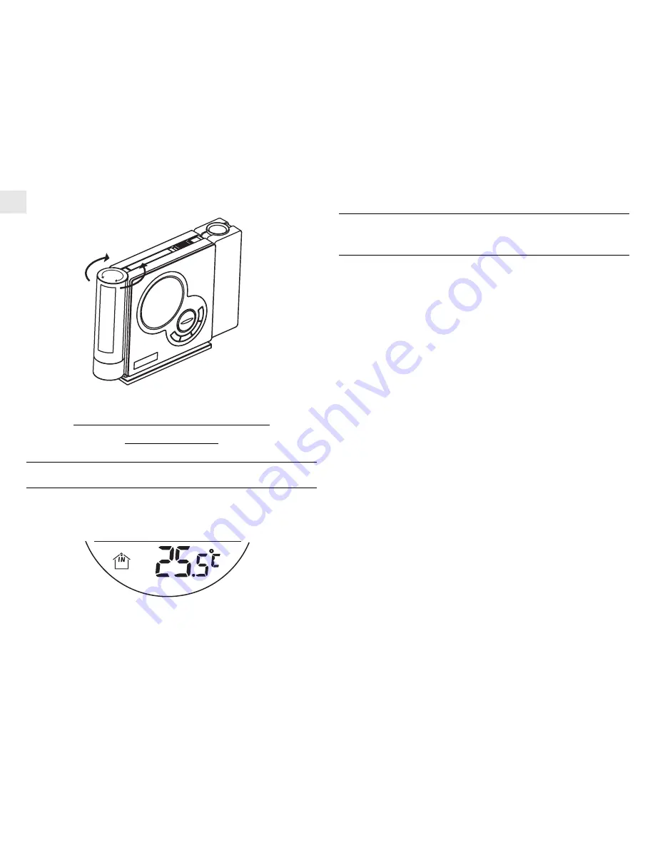
DISPLAY OF INDOOR TEMPERATURE

Once batteries are installed into the main unit, it will start to detect
the indoor temperature and the data will be displayed.

Summary of Contents for Alpha C23 Boilers

Page 1: ...ion to indoor temperature display by means of a wireless remote thermo sensor this unit can simultaneously monitor the outdoor temperature The unit can record maximum and minimum indoor outdoor temperature readings No wire installation is required between the main and remote units as this unit operates at 433 MHz This unit featured with a projection function that allows the user to display either ...

Page 2: ...BUTTONS Press to display the alarm 1 or alarm 2 function Press and hold for 2 seconds to enter the corresponding alarm time setting mode A8 MODE BUTTON Press to toggle among the calendar clock display modes Press and hold for 2 seconds to enter the clock setting mode A9 BUTTONS Press to increase decrease the values in setting modes Press and hold for 2 seconds to activate deactivate the autorecept...

Page 3: ...BUTTON Slide to enable continuous projection when Adapter is connected C5 BATTERY COMPARTMENT Accommodates 2 pieces of UM 3 or AA 1 5 V batteries C6 RESET BUTTON Press to return all settings to default values C7 LIGHT SENSOR KNOB Rotate to adjust the sensitivity of the light sensor C8 C F BUTTON Selects between Centigrade C and Fahrenheit F BOTTOM VIEW D1 4 5 V DC JACK For AC power adapter install...

Page 4: ... between Centigrade C and Fahrenheit F D RESET BUTTON Returns all settings to default values E BATTERY COMPARTMENT Accommodates two UM 4 or AAA size 1 5V batteries F BATTERY DOOR G WALL MOUNT HOLDER Supports the remote unit in wall mounting H REMOVABLE TABLE STAND For standing the remote unit on a flat surface BATTERY INSTALLATION MAIN UNIT This unit can be operated by batteries or AC power alone ...

Page 5: ...s RESET 4 Replace the battery compartment door by rotating it back onto the unit by following the direction of Close When the battery power level is low the respective low battery indicator will light up Replace the batteries or connect it with AC power adapter Please note if onlyAC adapter is connected and no battery is installed low battery indicator for main unit will also light up Using AC Pow...

Page 6: ...6 Replace the battery compartment door and secure its screws 7 Position the remote sensor and main unit within effective transmission range which in usual circumstances is 30 meters Though the sensor is weather resistant and is meant for use outside it should be placed away from direct sunlight rain or snow Note The effective range may be limited by building materials and the position of either th...

Page 7: ...r for successful reception STRONG WEAK NO RECEPTION IN PROGRESS For best reception place the unit away from other equipment that emit radio frequency or microwave signals such as TVs radios PCs or microwave ovens Other causes for signal interference include electrical power transmission tower and or steel reinforced concrete construction HOW TO ENABLE OR DISABLE AUTO RECEPTION To disable the autom...

Page 8: ... MODE for 2 seconds The 2nd Zone time hour offset will start flashing 2 Enter the hour offset by using or Press MODE to confirm the entry 3 Follow the same procedures to set the 12 24 format hour minutes year mm dd or dd mm calendar display format month day display languages and hourly chime on off mode 4 Press MODE to save the changes and exit the setting mode If changes are made after the minute...

Page 9: ...and projection will activate for 5 seconds and the alarm sounds will be given out for 2 minutes To stop the alarm press any key When the SNOOZE LIGHT button is pressed to stop the alarm sound the snooze function will be activated and the alarm will go off again after 8 minutes To disable the snooze function press and hold the SNOOZE LIGHT button for 3 seconds or press other key to stop the alarm s...

Page 10: ... changes This Pre alarm function applies with Remote sensor only b To set the Pre alarm 1 After setting the alarm time as indicated above the unit will enter the Pre alarm setting mode automatically PRE AL icon will be shown and the time interval will be flashing 2 Use the or button to select the operating time interval for this pre alarm function You can choose from 00 15 30 45 and 60 minutes 3 P...

Page 11: ...k and calendar setting mode please refer to Section SETTING THE CLOCK AND CALENDAR MANUALLY Section II Nightlight NIGHTLIGHT FUNCTION This unit is attached with a LED Nightlight at the side which acts as a good bed side feature It can only be operated when AC power is connected to the unit To turn on the nightlight connect the unit to the AC power Slide the LIGHT AUTO ON OFF to the ON mode To turn...

Page 12: ...hing period reception of clock radio signal will be suspended If that fails check if the remote thermo sensor is still in place Try repositioning the units as they may be having temperature transmission block as a result of interference Note Failure of reception of remote signals may be due to the following reasons 1 Battery power of the units is too low Suggested Solution Replace with fresh batte...

Page 13: ...mperature readings recorded are lower or higher the measuring range LLL or HHH will be displayed respectively NOTE ON C AND F The outdoor temperature display on the main unit is dominated by the selection on the C F side switch of the main unit Whatever the display unit of the remote sensor is it will only apply to the remote sensor itself and the temperature will be automatically converted to the...

Page 14: ...neered to give you years of satisfactory service if you handle it carefully Here are a few precautions 1 Do not immerse the unit in water If you spill liquid over it dry it immediately with a soft lint free cloth 2 Do not clean the unit with any liquid containing alcohol detergent abrasive or corrosive materials They may scratch the plastic parts and corrode the electronic circuit 3 Do not subject...

Page 15: ...larm Dual daily alarm Temperature Measurement Main Unit Indoor Temperature Measuring Range 5 C to 50 C 23 F to 122 F Temperature Resolution 0 1 C 0 2 F Remote Unit Remote Temperature Measuring Range 20 C to 60 C 4 F to 140 F Temperature Resolution 0 1 C 0 2 F RF Transmission Frequency 433 MHz Temperature Sensing Cycle Approx 40 seconds Power Main Unit 2 pcs of AA sized or UM 3 1 5 V batteries 4 5 ...

Page 16: ...R TTE 1999 5 EC Directives if used for its intended use and that the following standard s has have been applied Efficient use of radio frequency spectrum Article 3 2 of the R TTE Directive applied standard s EN 300 220 1 2 3 1997 Electromagnetic compatibility Article 3 1 b of the R TTE Directive applied standard s ETS 300 683 1997 Safety of information technology equipment Article 3 1 a of the R T...

Page 17: ...emote Sensor and activate SEARCH mode in the Main Unit Displayed Temperature data are different from other measuring instruments 1 The measurement method is different 2 The area under evaluation is different or being influenced by climate 1 Use the same instruments with consideration of the tolerance of readings 2 Place the 2 instruments very closely for a time period no less then 30 minutes avoid...

Page 18: ...osition The Nightlight does not turn on i The AC DC Adaptor is not installed ii The light intensity of the environment is too high and Auto mode is selected The unit is reset when SNOOZE button is pressed Batteries are being discharged Replace with new batteries i Make sure the AC DC adapter is securely plugged into the unit and connected to the wall socket ii Reduce the light intensity in the env...

Reviews: