


2
GB
UM3 AA
UM3 AA
B
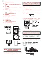
REMOTE THERMO SENSOR
B1
LCD
Displays the current temperature monitored by the remote
unit
B2
LED indicator
Flashes when the remote unit transmits data to the main
display unit
B3
°C/°F slide switch
Selects between Centigrade (°C) and Fahrenheit (°F)
B4
[
] Low-battery indicator
Appears when the battery power is low
B5
RESET button
Returns all settings to default values
B6
Battery compartment
Accommodates two UM-3 or AA size batteries
B7
BATTERY DOOR
B8
Wall-mount holder
Use to mount remote sensor on a wall
B9
Removable table-stand
For standing the remote unit on a flat surface
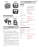
BATTERY INSTALLATION AND REMOTE
THERMO-SENSOR SETUP
Follow this step-by-step procedure for installing batteries and
setting up the remote-sensor unit. Successful setup should ensure
that temperature signals are properly received.
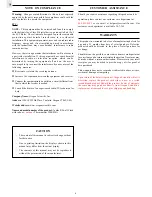
Note: The effective range may be limited by building
materials and the position of either the main unit or the
r e m o t e t h e r m o - s e n s o r u n i t . T r y v a r i o u s s e t - u p
arrangements for best result.
Setting up the thermo-sensor unit:
1. Position the remote sensor within the signal transmission
range of the main display unit. The maximum transmission
range is 100 feet (30 metres).
2. Remove the screws of the battery door on the remote thermo-
sensor unit.
3. Select display of temperature in either °C or °F using the
°C/°F slide switch.
4. Install into the thermo-sensor unit, two UM-3 or "AA" size
1.5V batteries strictly according to the polarities shown.
5. Replace the battery compartment door and secure its screws.
Note: Though the sensor is splash proof and is meant for
use outside, it should be placed away from direct sunlight,
rain, or snow.
Once the batteries have been inserted into the remote thermo-
sensor unit, batteries can now be inserted into the main unit.
BATTERY INSTALLATION : MAIN UNIT
This unit
requires two (2) UM-3 or “AA” size batteries for operation.
How to insert batteries into the main unit:
1. Press the door tab and click-open the door.
2. Insert the batteries strictly according to the polarities shown
therein.
CHANNEL
1 2 3
RESET
˚C
˚F
2
B1
B2
B3
B5
B4
B6
B7
B8
B9
Summary of Contents for Jumbo JMR828A
Page 7: ...7 GB...