background image

08.05/WE

29

ORGAPACK CR 208 P

6

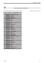
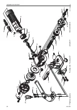
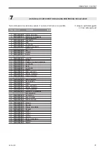
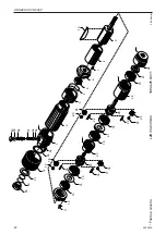
LISTE DES PIÈCES

1831.003.001/10

Lors d'une commande, veuillez indiquer le numéro d'article et de la pièce

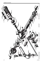
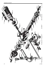
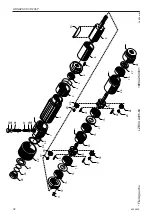
Vue éclatée à page 30

*

Pièces de rechange recommandées

 Pos. No d'article

Article

Pièce

 Pos. No d'article

Article

Pièce

1

1831.032.002

Bâti d’engrenage complet

1

2

1831.032.001

Plaque pour roulement

1

3

1832.039.002

Couvercle

1

4

1831.011.001

Plaque de base

1

5

1831.011.002

Raccord courbé, 0,8 - 1,0 mm

1

6

1821.080.001

Levier

1

7

1821.025.001

Ecrou

1

8

1821.034.002

Arbre

1

*

9

1821.040.001

Molette de tension

1

*

10

1821.043.001

Matrice de tension

1

11

1821.034.001

Axe

1

12

1821.020.010

Douille d’écartement

1

13

1821.063.001

Pignon ZTA

1

14

1821.063.002

Roue ZTA

1

15
16
17
18
19

20

1820.010.213

Resort à pression

1

21

1917.401.145

Rondelle, ø 14/26 x 0,5

2

22

1933.820.120

Douille à aiguilles, ø 20/26 x 12

1

23

1933.722.162

Douille à aiguilles, ø 22/28 x 16

1

24

1933.914.120

Douille à aiguilles, ø 14/20 x 12

2

25

1933.910.120

Douille à aiguilles, ø 10/14 x 12

1

26

1934.330.151

Butéee lisse, ø 15/28,4 x 6

1

27

1934.310.350

Butéee lisse, ø 35

1

28

1921.304.120

Goujon, ø 4m6 x 12

1

29

1910.505.082

Goujon fileté, M 5 x 8

1

30

1911.006.168

Vis cylindrique, M 6 x 16

2

31

1911.005.149

Vis cylindrique, M 5 x 14

4

32

1911.005.108

Vis cylindrique, M 5 x 10

2

33
34

1921.305.160

Goujon, ø 5m6 x 16

2

35
36

1919.606.072

Rondelle de sécurité, M 6

2

37

1919.605.062

Rondelle de sécurité, M 5

6

38
39

40

1921.306.220

Goupille élastique, ø 6m6 x 22

1

41

1912.908.006

Vis à anneau, M 6 (sur demande)

1

42
43
44
45
46
47
48
49

50

1894.425.000

Moteur à air comprimé,
LZB 33 A 005-64

1

51

1895.312.003

Coin

1

52
53
54
55
56
57
58
59

60
61
62
63
64
65
66
67

1820.090.068

Plaque de huile

1

68

1940.311.721

Raccord mâle, G 1/4"

1

69

1821.090.003

Plaque

1

Exécution USA/CAN

68

1820.100.019

Raccord mâle, 1/4" NPT

1

71

1820.100.017

Raccord de la passage,
G 1/4" x 1/4" NPT

1

Summary of Contents for CR 208 P

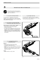
Page 1: ...PERA OPERA OPERATING TING TING TING TING AND SAFETY INSTR AND SAFETY INSTR AND SAFETY INSTR AND SAFETY INSTR AND SAFETY INSTRUCTIONS UCTIONS UCTIONS UCTIONS UCTIONS MODE D EMPLOI ET DE S CURIT MODE D...

Page 2: ...htlinie bereinstimmt Ber cksichtigteNormen EN 292 1 EN 292 2 EN 349 EN 983 EN 1050 prEN792 2 CH 8953Dietikon April2001 Manager Leiter Sales Marketing Technik R Kieffer M Binder CH ORGAPACK GmbH Packag...

Page 3: ...cke 0 6 1 00mm Zugfestigkeit bis ca 1100 N mm2 ORGAPACK VERSCHLIESSZANGEN OR V40P Einfachkerbung OR V41P Doppelkerbung ORGAPACK PLOMBEN Bandbreite 19 mm CSP 617 Bandbreite 25 mm CSP 717 Bandbreite 32...

Page 4: ...bung und die Wartung Neben der Betriebsanleitung und den im Verwender land und an der Einsatzstelle geltenden Regelungen zurUnfallverh tungsindauchdieanerkanntenfach technischenRegelnf rsicherheit und...

Page 5: ...enentspre chen Bestimmungsgem sse Verwendung Dieser Spannapparat ist zusammen mit einer Ver schliesszange zum Umreifen von runden schweren Packst cken Profilbunde Rohre usw bestimmt Der Apparat wurde...

Page 6: ...Fig 3 Den Bandanfang 2 1 unter der Plombe umbiegen 3 4 cm Umreifung von Hand anziehen und das von der Rolle kommende Band mit der linken Hand ca 20 cm von der Plombe entfernt festhalten Apparat mit de...

Page 7: ...annungeinstellen berDruck reduzierventilanderWartungseinheit siehe Kapitel 5 1 Fig 4 Fig 5 Verschliessen Mit Verschliesszange B nder verschliessen siehe Betriebsanleitung OR V 40 P OR V 41 P Fig 6 Ban...

Page 8: ...eiZylinderschrauben 8 1 l sen Lagerplatte 8 2 vorsichtigvonderSpannwelle abziehen Gegenscheibe 8 3 und Spannrad 8 4 abzie hen Spannrad kontrollieren evt reinigen oder ersetzen Einbau Der Einbau erfolg...

Page 9: ...x 12 1 26 1934 330 151 Axiallager 15 28 4 x 6 1 27 1934 310 350 Axiallager 35 1 28 1921 304 120 Zylinderstift 4m6 x 12 1 29 1910 505 082 Gewindestift M 5 x 8 1 30 1911 006 168 Zylinderschraube M 6 x 1...

Page 10: ...CK CR 208 P CR 208 P 1831 003 001 8 51 50 7 26 20 22 13 1 27 32 37 3 21 14 b 31 37 25 6 11 5 29 4 10 23 8 12 9 21 40 37 2 24 24 e 68 b 30 36 28 69 02 12 04 sm hp 41 b Loctite 243 e Loctite 577 e 71 b...

Page 11: ...32 025 Gewindeb chse 1 21 1894 432 024 Tellerfeder 2 22 1894 432 017 Achse 2 23 1894 332 024 Lagernadel 32 24 1894 432 016 Planetenrad 2 25 1894 432 018 Planetenwelle 1 26 1894 432 023 Getriebegeh use...

Page 12: ...ORGAPACK CR 208 P 15 15 27 28 21 1 13 12 11 20 24 23 26 3 2 5 7 6 10 9 8 4 16 18 17 25 16 17 18 23 24 15 15 22 22 1894 425 000 1 28 5 98 wb ja 19 LZB 33 A005 64 14 33 32 29 35 36 37 38 39 40 31 30 34...

Page 13: ...OF CONTENTS 1 Technical data 13 2 General information 14 2 1 Information on environmental protection 14 2 2 Compressed airconnection 14 3 Safetyinstructions 15 4 Operatinginstructions 16 4 1 Operating...

Page 14: ...f operating material fault elimination and maintenance In addition to the operating instructions and the regu lations for accident prevention effective in the country of use and place of application t...

Page 15: ...break Caution Danger of squeezing Do not put your fingers into the tension wheel area Caution Only strap packed goods Do not put hands or other parts of the body between the strap and the package dur...

Page 16: ...econd time through the seal Fig 1 Fig 2 Fig 3 Bend the strap start below the seal 3 4 cm 1 2 Pull the strap tightly by hand and take a portion of the strap leading to the dispenser with the left hand...

Page 17: ...e motor For adjustment of strap tension by pressureregulatoronmaintenanceunit see chapter 5 1 Fig 4 Fig 5 Sealing Seal the straps using sealer see operating instruc tion OR V 40 P OR V 41 P Fig 6 Cut...

Page 18: ...e air supply Loosen two cylinder screw 8 1 Carefullyremovethebearingplate 8 2 fromtension shaft Take off the counter washer 8 3 and the tensioning wheel 8 4 Check the tensioning wheel clean or replace...

Page 19: ...x 12 1 23 1933 722 162 Needle bushing 22 28 x 16 1 24 1933 914 120 Needle bushing 14 20 x 12 2 25 1933 910 120 Needle bushing 10 14 x 12 1 26 1934 330 151 Trust bearing 15 28 4 x 6 1 27 1934 310 350 T...

Page 20: ...CR 208 P CR 208 P 1831 003 001 8 51 50 7 26 20 22 13 1 27 32 37 3 21 14 b 31 37 25 6 11 5 29 4 10 23 8 12 9 21 40 37 2 24 24 e 68 b 30 36 28 69 02 12 04 sm hp 41 b Loctite 243 e Loctite 577 e 71 b 31...

Page 21: ...0 1894 432 025 Threaded bushing 1 21 1894 432 024 Saucer spring 2 22 1894 432 017 Shaft 2 23 1894 332 024 Bearing needle 32 24 1894 432 016 Planetary wheel 2 25 1894 432 018 Planetary cage 1 26 1894 4...

Page 22: ...APACK CR 208 P 15 15 27 28 21 1 13 12 11 20 24 23 26 3 2 5 7 6 10 9 8 4 16 18 17 25 16 17 18 23 24 15 15 22 22 1894 425 000 1 28 5 98 wb ja 19 LZB 33 A005 64 14 33 32 29 35 36 37 38 39 40 31 30 34 Lef...

Page 23: ...m CSP 817 1 Donn es techniques 23 2 Instructions g n rales 24 2 1 Remarque relative la protection de l environnement 24 2 2 Raccordementpneumatique 24 3 Instruction de s curit 25 4 Mode d emploi 26 4...

Page 24: ...l Elles doivent tre lues et appliqu es par toutes les person nes qui sont charg es de travaux sur l appareil Ces travaux comprennent en particulier le service l alimen tation des consommables l limina...

Page 25: ...peut se casser quand il est tendu Prudence danger d crasement Ne touchez pas la molette et l environnement avec les doigts Prudence cercler uniquement le paquet Ne mettez pas la main ou d autres parti...

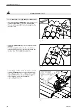
Page 26: ...r le feuillard 2 1 de 3 4 cm sous l agrafe Tendre le feuillard la main en le tenant dans la main gauche une distance d environ 20 cm de l agrafe 4 MODE D EMPLOI Fig 1 Fig 2 1 1 Fig 3 De la main droite...

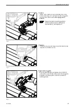
Page 27: ...as arr ter le moteur R glage de la force de tension par le r ducteurdepressiondugroupelubri ficateur voirchapitre5 1 Fig 4 Fig 5 Sertissage Sertissageavecpincedefermeture voirmode d emploi OR V 40 P O...

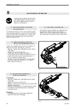
Page 28: ...ppareilduraccordementd air Enlever les deux vis cylindrique 8 1 Retirer la plaque roulement 8 2 de l arbre de tension Retirer la rondelle contre 8 3 et la molette de tension 8 4 Voir la molette de ten...

Page 29: ...les 20 26 x 12 1 23 1933 722 162 Douille aiguilles 22 28 x 16 1 24 1933 914 120 Douille aiguilles 14 20 x 12 2 25 1933 910 120 Douille aiguilles 10 14 x 12 1 26 1934 330 151 But ee lisse 15 28 4 x 6 1...

Page 30: ...CK CR 208 P CR 208 P 1831 003 001 8 51 50 7 26 20 22 13 1 27 32 37 3 21 14 b 31 37 25 6 11 5 29 4 10 23 8 12 9 21 40 37 2 24 24 e 68 b 30 36 28 69 02 12 04 sm hp 41 b Loctite 243 e Loctite 577 e 71 b...

Page 31: ...0 1894 432 025 Douille filet 1 21 1894 432 024 Rondelle bomb e 2 22 1894 432 017 Axe 2 23 1894 332 024 Aiguille 32 24 1894 432 016 Roue plan taire 2 25 1894 432 018 Arbre plan taire 1 26 1894 432 023...

Page 32: ...ORGAPACK CR 208 P 15 15 27 28 21 1 13 12 11 20 24 23 26 3 2 5 7 6 10 9 8 4 16 18 17 25 16 17 18 23 24 15 15 22 22 1894 425 000 1 28 5 98 wb ja 19 LZB 33 A005 64 14 33 32 29 35 36 37 38 39 40 31 30 34...

Page 33: ...hezza 25 mm CSP 717 Larghezza 32 mm CSP 817 1 Dati tecnici 33 2 Informazioni generali 34 2 1 Informazioni relative alla protezione dell ambiente 34 2 2 Raccordoariacompressa 34 3 Prescrizioni di sicur...

Page 34: ...e costantemente disponibili presso la macchina Esse devono venire lette da tutto il personale incaricato dell uso della macchina In parti colare importante il modo di impiego l eliminazione dei distur...

Page 35: ...cordicorrispondenti alle prescrizioni di sicur ezza Utilizzazione secondo le norme Questo apparecchio destinato alla reggiatura per colli rotondi et pesanti con pinze di chiusura Questo apparecchio st...

Page 36: ...e l inizio della reggetta 2 1 sotto il piombo 3 4cm Tirare la reggiatura manualmente e con la mano sinistra tenere ferma la reggetta proveniente dal rotolo a circa 20 cm distante dal piombo Tenere l a...

Page 37: ...egolarelatensionedellareggetta di riduzionedellapressionedell unit di manutenzione vedicapitolo5 1 Fig 4 Fig 5 Chiudere Chiudure con pinze di chiusura vedi le istruzioni per l uso OR V 40 P OR V 41 P...

Page 38: ...a piastrina del cuscinetto 8 2 dall alberoditensione Estrarre la rondella 8 3 e la rotella di tensione 8 4 Controllare e eventualmente pulire o sostituire la rotella di tensione Montaggio Ilmontaggioa...

Page 39: ...12 1 23 1933 722 162 Cuscinetto a rullini 22 28 x 16 1 24 1933 914 120 Cuscinetto a rullini 14 20 x 12 2 25 1933 910 120 Cuscinetto a rullini 10 14 x 12 1 26 1934 330 151 Assiale 15 28 4 x 6 1 27 193...

Page 40: ...CR 208 P CR 208 P 1831 003 001 8 51 50 7 26 20 22 13 1 27 32 37 3 21 14 b 31 37 25 6 11 5 29 4 10 23 8 12 9 21 40 37 2 24 24 e 68 b 30 36 28 69 02 12 04 sm hp 41 b Loctite 243 e Loctite 577 e 71 b 31...

Page 41: ...cinetto 1 14 1894 432 013 Molla 1 15 1894 432 021 Cuscinetto 4 16 1894 332 015 Albero 2 17 1894 332 016 Stelo cuscinetto 2 18 1894 422 003 Rotella planetare 2 19 1894 422 004 Albero planetare 1 20 189...

Page 42: ...APACK CR 208 P 15 15 27 28 21 1 13 12 11 20 24 23 26 3 2 5 7 6 10 9 8 4 16 18 17 25 16 17 18 23 24 15 15 22 22 1894 425 000 1 28 5 98 wb ja 19 LZB 33 A005 64 14 33 32 29 35 36 37 38 39 40 31 30 34 Fil...

Reviews: