background image

2

Antenna Connection

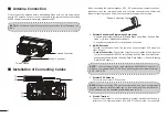
Please connect an antenna before transmitting. Make sure you are using a good 
quality VHF antenna, Connect the antenna cable to the rear antenna socket using a 

PL259 coaxial connector with natural impedance 50Ω.

NOTE:

 Do not transmit without an antenna connected as this will damage the 

radio.

To the Antenna

Antenna Connector

Feeder Connector

Installation of Connecting Cables


When connecting the external speaker, GPS, DC power supply, computer and nav-
igation device by the rear panel cable end, cover the connectors and cables with 
rubber vulcanzing tape as below, to prevent water seeping into the radio.

Rubber Vulcanzing Tape

1.■ 

External Speaker and Programming Data Leads

• Connect an external speaker to Blue and Black Lead. Blue→Positive Elec

-

trode (+), Black→Negative Electrode (-).

• 

Connect programming cable to Orange and Grey Lead.

2.■ 

NMEA/Out Leads

Through the rear panel lead, this radio can connect output GPS signals to 
other devices.

•■

Output Connection:

 Connect the output to the navigation device input line 

(port) that supports NMEA0183 for receiving location data from other ships, 

connect as follows: Brown→Sending Data, Data Output (-); White→Sending 

Data, Data Output (+).

NOTE:

 The output signal of this radio complies with NMEA0183 version 2.0 

or above, compatible with DSC, DSE navigation equipment, statement format 
RMC, GSA, GSV.

3.■ 

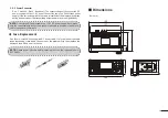
External GPS Antenna

Connect to an external GPS antenna.

NOTE:

 Make sure that the GPS antenna is installed in an open, unobstructed 

position so that the satellite signal can be received well. When installing the 

GPS antenna, use the supplied double-sided tape to fix it.

4.■ 

Ground Terminal

Connect this terminal to a vessel ground to prevent electrical shocks and in-
terference from other equipment. Use a PH M3×6 mm screw (not supplied).

Summary of Contents for MX1100G

Page 1: ...to IPX7 Independent Class B DSC Dedicated Receiver Speaker Vibration Draining Function Built in GPS Receiving Module The MX1100G meets IPX7 standard This is capable of withstanding water immersion of...

Page 2: ...not operating on another chan nel False or fraudulent distress calls are prohibited by law Privacy Information overheard but not intended for you cannot be used in any way by law Offensive or disrespe...

Page 3: ...ou enter your MMSI number Bypass entry of the MMSI by pressing the BACK button please see page 14 for MMSI code programming WARNING When transmitting keep your body or head more than 20cm from the ant...

Page 4: ...n Water Draining Function 11 Microphone Lock Function 11 SCAN OPERATION Scan Types 12 Setting TAG Channels 12 Starting a Scan 12 DUALWATCH TRI WATCH Description 13 Operation 13 DSC OPERATION MMSI Code...

Page 5: ...plied with your radio allows overhead or dash board mounting 1 Fix the mounting bracket to overhead or dashboard with the supplied screws and mount the radio to the mounting bracket with the knob bolt...

Page 6: ...e Electrode Connect programming cable to Orange and Grey Lead 2 NMEA Out Leads Through the rear panel lead this radio can connect output GPS signals to other devices Output Connection Connect the outp...

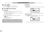
Page 7: ...Connect the DC power cable to a 13 8V DC power supply Note make sure the correct polarity is observed connect red cable to positive and black cable to negative terminals Fuse Replacement One fuse is i...

Page 8: ...Rotate or press to enter the volume setting display interface then rotate to adjust the volume Press twice to enter the squelch level setting display interface then rotate to adjust the squelch In the...

Page 9: ...istress then to make a call is displayed NOTE NEVER make a distress call if your ship or a person is not in an emer gency A distress call should be made only when immediate help is needed 2 Other DSC...

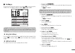
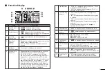
Page 10: ...s of backlight brightness 1 7 OFF 13 Log Press to display received call log or distress message log Microphone Microphone PTT Switch PTT Press and hold to transmit Release to receive Transmit Power Ke...

Page 11: ...fter receiving valid GPS data A manually input GPS data is valid for 23 5 hours and then a warning message is displayed 7 Scan Indicator SCAN 16 is displayed while Priority Scan SCAN is displayed whil...

Page 12: ...pears CH70 is for DSC transmitting only 3 Release PTT to receive NOTE Do not transmit without an Antenna as this will damage the radio If the TOT function is enabled by the PC programming software the...

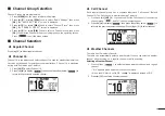
Page 13: ...i watch 1 Press 16 C to select Channel 16 2 Press to display then press the softkey below to return to the previously selected channel Call Channel Each regular channel group has a separate leisure us...

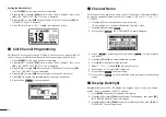
Page 14: ...Press softkey to cancel and exit Channel Name Each channel can be assigned a name of up to 10 characters Characters available for input 26 uppercase letters number 0 9 symbol _ SPACE 1 Press to selec...

Page 15: ...Vibration helps drain water away from the speaker housing water that might other wise muffle the sound coming from the speaker The radio makes a vibrating noise when this function is being used NOTE...

Page 16: ...s displayed on screen 4 To cancel the TAG channel setting press softkey again disappears from the screen Setting Clearing All Tagged Channels 1 Press MENU key the menu interface is displayed 2 Press o...

Page 17: ...annel while receiving on another channel DUALWATCH TRI WATCH Call Channel Operation 1 Press softkey to start Dualwatch or Tri watch DW 16 is displalyed during Dualwatch TW 16 is displalyed during Tri...

Page 18: ...the code 6 Enter MMSI code again to confirm 7 Repeat step 3 to 5 as above When your MMSI code input is successful MMSI Successfully Registered is displayed as below Once setup is complete the radio c...

Page 19: ...main interface Entering the Position and Time A Distress call should include the vessel s position and time If no GPS data is re ceived manually input the position and Universal Time Coordinated UTC t...

Page 20: ...to select the desired characters Press OK to input the characters Select or to move the cursor then press OK Press to select numbers characters and letters 7 Then press softkey to save and return to...

Page 21: ...Individual ACK Auto Able Auto Unable Manual Position ACK Auto Able Manual Polling ACK Auto Manual Test ACK Auto Manual Channel Auto Switch CH Auto SW Select whether or not to automatically switch to C...

Page 22: ...t When the transmitting and receiving DSC signals match OK is displayed If NG is displayed that means there is a problem with at least one of the transmitting DSC and the receiving DSC circuit Contact...

Page 23: ...me the countdown 4 When you receive an Acknowledgement an alarm sounds press to turn OFF the alarm 5 Hold down PTT and then talk to explain your situation 6 After you have finished your conversation t...

Page 24: ...OFF the alarm then hold down PTT to communicate A default Distress alert contains Nature of Distress Select as per Step 2 Position Information The latest GPS or manually entered position which is held...

Page 25: ...DSC Log Accept Accept the call Channel 16 is automatically selected Monitor Channel 16 as a coast station may require assistance After Channel 16 is selected you can select your next operation by pre...

Page 26: ...down PTT to communicate When you receive an Acknowledgement Unable to comply an alarm sounds the Acknowledge information is displayed Press then press to return to the operating screen 10 After commun...

Page 27: ...ores the call and returns to the operating screen blinks continuously until you display the call message The call is saved in the DSC Log Press Able to comply sends an Individual Acknowledgement call...

Page 28: ...s displayed NOTE You can also display the OTHER DSC screen by selecting the DSC Call item on the Menu screen 2 Select Type then press OK MESSAGE TYPE is displayed 3 Select Group then press OK or softk...

Page 29: ...Log Press Accepts the call The assigned channel is automatically selected The call is saved in the DSC Log Press Closes the Group call then returns to the operating screen Press The receiver call s in...

Page 30: ...ress the softkey for the next operation Press Ingores the call and returns to the operating screen The call is saved in the DSC Log blinks continuously until you display the call message Press Pauses...

Page 31: ...K 5 Select a target to send a Position Request call to and then press OK or softkey NOTE You can also select Manual Input to manually enter the target ID 6 Press softkey to send the Position Request c...

Page 32: ...call NOTE If the Auto ACK function in DSC Settings is set to Auto the Position Reply is automatically sent to the calling station However even if the Auto ACK function is set to Manual after receiving...

Page 33: ...een the two stations involved Sending a Test Call 1 Press softkey the OTHER DSC screen is displayed NOTE You can also display the OTHER DSC screen by selecting the DSC Call item on the Menu screen 2 S...

Page 34: ...VD TEST CALL is displayed 1 Press softkey to turn OFF the alarm 2 Press the softkey for the next operation Press Ingores the call and returns to the operating screen The call is saved in the DSC Log b...

Page 35: ...firmation screen is displayed 4 Press softkey to send the Acknowledgement Transmitting Test Ack is displayed 5 Press softkey a confirmation screen is displayed 6 Press to return to the operating scree...

Page 36: ...s softkey to display the received call s information Press Returns to the operating screen Press Returns to the previous screen Press Deletes the selected call log NOTE The confirmation screen is disp...

Page 37: ...has passed without any operation on a task the radio automati cally exits the Task mode and returns to the operating screen When a Time out Timer TOT activates an alarm sounds and a countdown message...

Page 38: ...tasks is displayed at the top of the screen The number of tasks On the TASK LIST screen the following softkeys are displayed Press Holds the task and returns to the operating screen Press Displays th...

Page 39: ...dress Address 27 Category Category 27 Mode Mode 27 Channel Channel 27 GPS Info Display Position Info Source Source Latitude LAT Longitude LON UTC Time UTC Speed SOG Course COG Configuration Backlight...

Page 40: ...AN TIMER ON OFF OFF 3 DUAL TRI WATCH Dualwatch Tri watch Dualwatch 4 CHANNEL GROUP USA INT CAN USA 5 CALL CHANNEL Channel 00 P3 Channel 09 6 WX ALERT ON with Scan ON OFF OFF 7 FAV SETTINGS Set All Cha...

Page 41: ...ault Resets favourite channels to the default FAV on MIC You can select the channel set when you press on the supplied microphone CH Display You can select the number of digits to display the channel...

Page 42: ...when a screen that is not related to DSC is displayed DSC Default 15 min Setting for when a screen that is related to DSC is displayed Distress Default Off Setting for when a screen that is related t...

Page 43: ...25 156 525 87 87 87 157 375 157 375 08 08 08 156 400 156 400 24 24 157 200 161 800 71 71 71 156 575 156 575 88 88 88 157 425 157 425 09 09 09 156 450 156 450 25 25 157 250 161 850 72 72 72 156 625 156...

Page 44: ...ransmitter Output Power 25W 1W Max Frequency Deviation 5kHz Spurious Emissions 70dB H 56dB L Adjacent Channel Power 70dB Audio Harmonic Distortion 10 Current Consumption 5 5A H 1 5A L Input Impedance...

Page 45: ...is correct 2 External GPS format should be NMEA 0183 2 0 or 3 01 3 Unable to scan No TAG channel set Set the channels you want to scan as TAG channel 15 Unable to transmit Work on Weather Channel or...

Page 46: ...of All component parts removed under this Express Warranty become the property of Oricom In the unlikely event that your Oricom product has a recurring failure Oricom may always subject to the Competi...

Page 47: ...esented for repair may be replaced by refurbished goods or parts of the same type rather than being repaired Contact details for Oricom support and Express warranty claims in Australia Oricom Internat...

Page 48: ...Ref 12102020...

Page 49: ......

Reviews: