3
•
Pinion shaft type
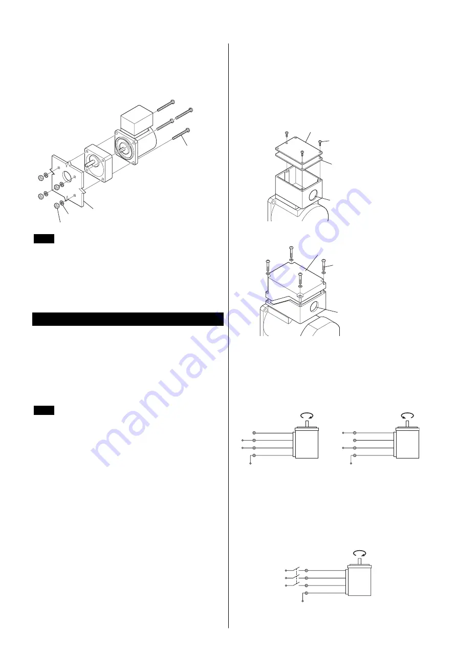
Drill holes on the mounting plate and fix the motor and gearhead on
the plate using screws supplied with the gearhead. Be careful there is
no gap between the motor flange and the gearhead.
For details of installation, see the operating manual provided with
the gearhead, which is sold separately.
Gearhead
Washer
Nut
Motor
Screw
(provided with
gearhead)
Mounting plate
Note
Use the gearhead with pinion shaft which is identical
with one of motor.
•
Motor with cooling fan
When installing a motor with cooling fan onto a device, leave
10 mm (0.39 in.) or more behind the fan cover or open a ventilation
hole so that the cooling inlet on the back of the motor cover is not
blocked.
Connection and operation
Insulate all the wire connections, such as the connection between the
motor and the capacitor connection.
When the single-phase motor is run in only one direction, unused
lead wires should be insulated.
Ground the motor using a Protective Earth lead wire (green/yellow).
The direction of motor rotation is as viewed from the side of the
motor’s output shaft. The motor rotates in a clockwise (CW) and
counterclockwise (CCW) direction.
Note
•
Make sure that the motor case temperature does not
exceed 90 °C (194 °F) during operation of the motor.
Operation exceeding case temperature 90 °C
(194 °F) may significantly deteriorate the coils and
ball bearings of the motor and shorten the motor’s life
span. Motor case temperature can be measured by
fixing a thermometer on the motor surface. It can also
be measured using thermo tape or a thermocouple.
Thermal Class: 130 (B)
•
To change rotation direction of the single-phase
motor, wait until the motor completely stops.
Otherwise its direction may not change or may take
much time to change.
Rotating direction of the gearhead output
shaft
The rotating direction of the gearhead output shaft may be opposite
that of the motor shaft, depending on the gear ratio. For the rotating
direction of the output shaft of a specific gearhead used, refer to the
operating manual for the gearhead.
Connection method to a terminal box
•
Open the terminal box and connect wires.
•
Use applicable cable ground and conduit for conduit opening.
•
After connecting, close the terminal box with the terminal cover.
•
Terminal cover screws tightening torque
Single-phase 25 W, 40 W/Three-phase: 0.3 N·m (2.6 lb-in)
Single-phase 60 W, 90 W: 1 N·m (8.8 lb-in)
•
Single-phase 25 W, 40 W/Three-phase
Rubber gasket
Terminal cover
Terminal cover
screw
Conduit opening
[Ø21.5 mm (Ø0.846 in.)]
•
Single-phase 60 W, 90 W
Terminal cover
Terminal
cover screw
Conduit opening
[Ø21.5 mm (Ø0.846 in.)]
Single-phase motors
•
Wiring diagram
Connect the motor according to the figure.
The connection method will vary, depending on the direction
Clockwise
CW
Black
White
Red
Motor
Green/yellow
L
NC
∗
N
PE
Counterclockwise
CCW
Black
White
Red
Motor
Green/yellow
L
NC
∗
N
PE
∗
NC: Not connect.
Three-phase motors
Connect the motor according to the figure.
When connected according to the connection diagram, the motor will
operate in the clockwise direction (CW) as viewed from the motor’s
output shaft. To change the direction of rotation, change any two
connections between U, V and W.
Clockwise
CW
Black
Red
White
Motor
Green/yellow
L2 (S)
L1 (R)
L3 (T)
PE


