background image

Connection

16

6-2 

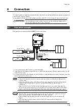
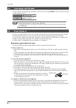
Connecting the main power supply and the control power supply 
(CN1)

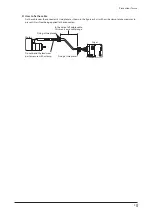
Connect a main power supply to the CN1 connector.
Connecting the control power supply allows you to continue monitoring even if the main power supply is shut off. 
Connect it as necessary.

Make sure the polarity of the power supply before connecting. Reverse-polarity connection may 
cause damage to the driver.


„

Applicable connector

Type

Part number

Applicable lead wire

Connector housing

1-1827864-2 (TE Connectivity)

AWG22 (0.34 to 0.37 mm

2

AWG20 (0.51 to 0.53 mm

2

AWG18 (0.85 to 0.87 mm

2

Lead wire insulation outer diameter:  
ø1.4 to 2.2 mm (ø0.055 to 0.087 in.) 
Lead wire insulation strip length: 
1.7 to 2.3 mm (0.067 to 0.091 in.)

Contact

1827589-2 (TE Connectivity)

Designated crimp tool

2119142-1 (TE Connectivity)


„

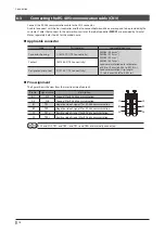
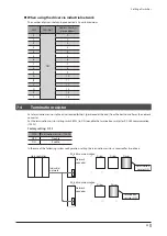
Pin assignment

The figure shows the view from the insertion side of contacts.

Pin No.

Name

Description

A1

GND

Ground

A2

GND

Ground

B1

Control power supply

+24 VDC/+48 VDC

B2

Main power supply

+24 VDC/+48 VDC

B1

A1

B2
A2

A1 and A2 are not electrically insulated.


„

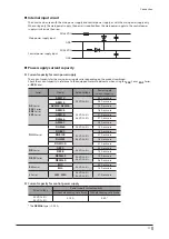
Voltage specifications

The voltage specifications of power supply input include the rated voltage and the allowable operating voltage.
The voltage specifications are common for the main power supply and the control power supply.

Rated voltage

24 VDC±5 % 
48 VDC±5 %

Allowable operating voltage

24 VDC input: 20 to 32 VDC (22.8 to 32 VDC) * 
48 VDC input: 40 to 55 VDC


* The value in parentheses ( ) is the one when the electromagnetic brake motor is connected.

Set the “main power mode” parameter to “0: 24 VDC” or “1: 48 VDC” when the main power supply 
starts up slowly or the voltage of the main power supply is unstable. (

_

p.50)

Summary of Contents for Astep AZ Series

Page 1: ...es product handling procedures and safety precautions Please read it thoroughly to ensure safe operation Always keep the manual where it is readily available HM 60440 AZ Series Motorized Actuator equi...

Page 2: ...21 7 Setting of switches 23 7 1 Protocol 23 7 2 Transmission rate 23 7 3 Address number slave address 24 7 4 Termination resistor 25 8 ID share mode 26 8 1 Overview of ID share mode 26 8 2 Flow of set...

Page 3: ...the following operating manuals for motors and motorized actuators OPERATING MANUAL Motor Edition OPERATING MANUAL Actuator Edition Motorized Actuator OPERATING MANUAL Function Setting Edition How to...

Page 4: ...ork Before starting operation 5 Installation 6 Connection Installation and connection 7 Setting of switches Setting of switches 9 Address and code lists Setting of parameters 4 Parameters 6 Method of...

Page 5: ...so executing and stopping operation can be controlled Operation data and parameters can also be set using the support software MEXE02 1 4 System configuration Control power supply 1 Circuit breaker 2...

Page 6: ...damage to equipment Do not transport install connect or inspect the product while the power is supplied Doing so may result in electric shock Do not touch the driver while the power is on Doing so may...

Page 7: ...only in the specified combination An incorrect combination may cause a fire Take measures against static electricity when operating the switches of the driver Failure to do so may result in the driver...

Page 8: ...seconds after the completion of writing the data Doing so may abort writing the data and cause an alarm of EEPROM error to generate The non volatile memory can be rewritten approximately 100 000 time...

Page 9: ...as shown in the figure or fix it with a wide clamp to take measures to prevent stress from being applied to the connectors Motor Driver In the case of a flexible cable this area is a movable range Fix...

Page 10: ...te Power supply type Product type Applicable Series Model name representing Series name 1 Example of model name DC power input Stepping motor AZ Series AZM AZM46AK Motorized actuator EAC Series 2 EACM...

Page 11: ...with the address number setting switch SW2 Factory setting OFF No 2 Sets the RS 485 communication protocol Factory setting ON No 3 Sets the transmission rate of RS 485 communication Factory setting ON...

Page 12: ...m message generated can be checked by counting the number of times the LED blinks The LED is lit in green when the alarm is reset Blinking blue Information is being generated The LED is lit in green w...

Page 13: ...ontinuous vibration or excessive shocks Area free of excessive electromagnetic noise from welders power machinery etc Area free of radioactive materials magnetic fields or vacuum Up to 1 000 m 3 300 f...

Page 14: ...Installation 14 Dimensions Unit mm in Mass 56 g 1 98 oz 41 1 61 47 1 85 53 2 09 R1 75 0 069 R 1 7 5 0 0 6 9 40 1 57 47 1 85 3 0 12 3 0 12 2 0 08 24 0 94 0 25 0 01...

Page 15: ...cessary 3 It is recommended that a circuit breaker or a circuit protector is connected because incorrect wiring may cause the internal input circuit to short circuit Connect the connectors securely In...

Page 16: ...Connectivity Designated crimp tool 2119142 1 TE Connectivity Pin assignment The figure shows the view from the insertion side of contacts Pin No Name Description A1 GND Ground A2 GND Ground B1 Contro...

Page 17: ...Series Model Rated voltage Power supply current capacity AZ Series EAC Series EAS Series EZS Series AZM14 24 VDC 5 0 4 A or more AZM15 0 5 A or more AZM24 AZM26 1 4 A or more AZM46 24 VDC 5 48 VDC 5...

Page 18: ...mm2 AWG22 0 37 mm2 Lead wire insulation outer diameter 1 08 to 1 9 mm 0 043 to 0 075 in Lead wire insulation strip length 1 7 to 2 3 mm 0 067 to 0 091 in Contact 1827588 2 TE Connectivity Designated...

Page 19: ...ctrically insulated SW3 is a double pole double throw switch Driver 1st unit SG RS 485 1 SG TR TR SG TR TR 120 1 k 1 k 5 V SG SG SW3 SW3 Driver 2nd unit SG TR TR SG TR TR 120 1 k 1 k 5 V SG SG SW3 SW3...

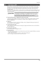
Page 20: ...s is effective in suppressing the electrical noise emitted from the motor Cover the driver by a metal plate such as aluminum This is effective in shielding the electrical noise emitted from the driver...

Page 21: ...erference in such environments z Connecting the main power supply and the control power supply Use DC power supplies compliant with EMC for he main power supply and the control power supply Use shield...

Page 22: ...aking the heat sink contact directly with the grounded panel 2 An Oriental Motor cable is used The driver uses components that are sensitive to static electricity Take measures against static electric...

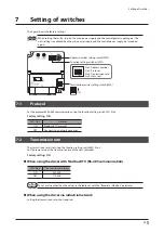
Page 23: ...otocol Set the protocol of RS 485 communication using the function setting switch SW1 No 2 Factory setting ON SW1 No 2 Protocol ON Modbus RTU protocol OFF Connects to a network converter 7 2 Transmiss...

Page 24: ...nnected is different between Modbus RTU RS 485 communication and industrial network When using the driver with Modbus RTU RS 485 communication The number of drivers that can be connected is 31 units m...

Page 25: ...end from the host controller or the network converter Set the termination resistor setting switch SW3 to ON to enable the termination resistor for RS 485 communication 120 Factory setting OFF SW3 Term...

Page 26: ...slave that shares the communication ID Unlike the broadcast mode different information can be written to multiple slaves at one time When a query is sent from the master each slave executes the proces...

Page 27: ...rite data 1 0030h 48 Direct data operation starting changing rate Upper 09ACh 2476 Lower 09ADh 2477 Share write data 2 0031h 49 Direct data operation stopping deceleration Writing a value ID share reg...

Page 28: ...e address 2 Slave address 1 Motor operation Slave address 2 Motor operation Corresponding function code Function codes and message lengths supported by the ID share mode are shown below Function code...

Page 29: ...the communication ID 1 to 31 1 0984h 2436 0985h 2437 Share control local ID Sets an ID for identifying a slave Data is read written in the order of ID set here Set a number of ID consecutively starti...

Page 30: ...e to register address 3 upper 00h Value written to register address 0983h Share control number lower 0002h Value write to register address 3 lower 02h Value write to register address 4 upper 00h Value...

Page 31: ...55 Share read data 3 0998h 2456 0999h 2457 Share read data 4 099Ah 2458 099Bh 2459 Share read data 5 099Ch 2460 099Dh 2461 Share read data 6 099Eh 2462 099Fh 2463 Share read data 7 09A0h 2464 09A1h 24...

Page 32: ...p absolute positioning RVS 12 Wrap absolute push motion 13 Wrap proximity push motion 14 Wrap push motion FWD 15 Wrap push motion RVS 16 Continuous operation speed control 17 Continuous operation push...

Page 33: ...osition Indicates the present command position When the wrap function is enabled the value on the wrap coordinates is indicated R 0064h 100 Command speed r min Indicates the present command speed r mi...

Page 34: ...I O Arrangement of bits _p 47 R 00B9h 185 I O status 2 R 00BAh 186 I O status 3 R 00BBh 187 I O status 4 R 00BCh 188 I O status 5 R 00BDh 189 I O status 6 R 00BEh 190 I O status 7 R 00BFh 191 I O sta...

Page 35: ...ister address 2 lower 00h Value write to register address 3 upper 00h Value write to register address 3 lower 7Ch Value write to register address 4 upper 00h Value written to register addresses 0994h...

Page 36: ...to be written to the driver of the slave address 1 Query unicast mode Field name Data Description Slave address 01h Driver of slave address 1 Function code 10h Writing to multiple holding registers D...

Page 37: ...riting to multiple holding registers 10h Read write Read write of multiple holding registers 17h When Read write of multiple holding registers 17h of the function code is used write is executed first...

Page 38: ...ess Slave address 1 Slave address 2 Value read Corresponding decimal Value read Corresponding decimal Present alarm upper 0000h 0 Share read data 0 upper 0000h 0 0000h 48 Present alarm lower 0001h 1 S...

Page 39: ...pending on the monitor value Error check for between slaves upper 3 10h Data 2 Value read from ID share register address upper 00h Value read from ID share register address 0000h Present alarm upper 0...

Page 40: ...per 00h Number of registers to be written from the starting ID share register address 12 registers 000Ch 1 Number of registers lower 0Ch Number of data bytes 18h Twice the number of registers in the q...

Page 41: ...r address 0004h Direct data operation stopping deceleration upper 0000h Value write to ID share register address 4 lower 00h Value write to ID share register address 5 upper 13h Value written to ID sh...

Page 42: ...decimal Present alarm upper 0000h 0 Share read data 0 upper 0000h 0 0000h 48 Present alarm lower 0001h 1 Share read data 0 lower 0000h 0030h Driver temperature upper 0002h 2 Share read data 1 upper 00...

Page 43: ...o ID share register address 1 upper 07h Value written to ID share register address 0001h Direct data operation operating speed lower 07D0h Value write to ID share register address 1 lower D0h Value wr...

Page 44: ...rom ID share register address 5 lower AAh Error check for between slaves lower 3 A2h Calculation result of CRC 16 The value varies depending on the monitor value Error check for between slaves upper 3...

Page 45: ...check lower 00h Calculation result of CRC 16 Error check upper 00h 1 Slave address 1 Share control local ID 1 2 Slave address 2 Share control local ID 2 3 Whenever data is sent to each slave error che...

Page 46: ...d the virtual input Arrangement of bits _p 47 206Ah 8298 0148h 328 0149h 329 Main power supply voltage Indicates the voltage of the main power supply 1 0 1 V 20A4h 8356 014Ah 330 014Bh 331 DIP SW Indi...

Page 47: ...4 Bit 3 Bit 2 Bit 1 Bit 0 z I O status The arrangement of bits for internal I O is indicated Input signals Modbus communication Register address Description Industrial network Command code 0170h 368...

Page 48: ...t 3 Bit 2 Bit 1 Bit 0 Output signal Modbus communication Register address Description Industrial network Command code 0178h 376 Bit 15 Bit 14 Bit 13 Bit 12 Bit 11 Bit 10 Bit 9 Bit 8 20BCh 8380 MAREA T...

Page 49: ...DY NEXT LAT JUMP1 LAT JUMP0 LAT Bit 7 Bit 6 Bit 5 Bit 4 Bit 3 Bit 2 Bit 1 Bit 0 DELAY BSY SEQ BSY PAUSE BSY OPE BSY SPD LMTD CRNT LMTD 017Eh 382 Bit 15 Bit 14 Bit 13 Bit 12 Bit 11 Bit 10 Bit 9 Bit 8 2...

Page 50: ...pper Lower READ WRITE 03FAh 1018 03FBh 1019 Main power mode Sets the voltage mode of the main power supply The voltage mode of the main power supply is discriminated in 50 ms after the main power supp...

Page 51: ...to be indicated by the POWER ALARM LED and the C DAT C ERR LED Setting range Check with the table below Initial value 1 A 01F5h 501 11F5h 4597 03F4h 1012 03F5h 1013 LED OUT BLUE function I O status o...

Page 52: ...moval function setting parameters All parameters are disabled not compatible I O parameters Modbus communication Register address Name Industrial network Command code Upper Lower READ WRITE 0E18h 3608...

Page 53: ...7 BREAK ATSQ 8 ALM RST 9 P PRESET 10 EL PRST 13 LAT CLR 14 INFO CLR 16 HMI 18 CCM 21 T MODE 22 CRNT LMT 23 SPD LMT 26 FW BLK 27 RV BLK 28 FW LS 29 RV LS 30 HOMES 31 SLIT 32 START 33 SSTART Assignment...

Page 54: ...CRNT LMT_R 81 R1_R 164 AREA4 23 SPD LMT_R 82 R2_R 165 AREA5 26 FW BLK_R 83 R3_R 166 AREA6 27 RV BLK_R 84 R4_R 167 AREA7 28 FW LS_R 85 R5_R 168 MPS 29 RV LS_R 86 R6_R 169 MBC 30 HOMES_R 87 R7_R 180 US...

Page 55: ...RIO 225 INFO POSERR 226 INFO DRVTMP 227 INFO MTRTMP 228 INFO OVOLT 229 INFO UVOLT 230 INFO OLTIME 232 INFO SPD 233 INFO START 234 INFO ZHOME 235 INFO PR REQ 237 INFO EGR E 238 INFO RND E 239 INFO NET...

Page 56: ...ny of the mounting screws secured the driver is loose Check if any of the connection parts of the driver is loose Check if dust is deposited on the driver Check if the driver has unusual smells or app...

Page 57: ...ed Execution disable due to non volatile memory processing in progress 8Ah Out of setting range 8Ch An exception response exception code 03h 04h was detected Command execute disable 8Dh An exception r...

Page 58: ...occurred consecutively by the number of times set in the Communication error detection Modbus parameter 85h RS 485 communication timeout The time set in the Communication timeout Modbus parameter has...

Page 59: ...here is generated Alarm code Number of LED blinks Alarm type Cause Remedial action How to reset 22h 3 Overvoltage The voltage of the main power supply exceeded the permissible value A large load inert...

Page 60: ...operation elevating operation was performed The voltage of the main power supply fell below the value set in the Overvoltage information parameter Undervoltage INFO UVOLT The voltage of the main power...

Page 61: ...formed Check the operation data When JOG operation high speed JOG operation or continuous macro operation is performed the input in the forward direction and that in the reverse direction are simultan...

Page 62: ...or the voltage of the main power supply is unstable Set the Main power mode parameter to 0 24 VDC or 1 48 VDC according to the rated voltage of the main power supply The electromagnetic brake is not p...

Page 63: ...on cable When installing the motor on a moving part use a flexible cable z Connection cables For motor encoder Model Length m ft CCM005Z2AAF 0 5 1 6 CCM010Z2AAF 1 3 3 CCM030Z2AAF 3 9 8 CCM050Z2AAF 5 1...

Page 64: ...05Z2ABF 0 5 1 6 CCM010Z2ABF 1 3 3 CCM030Z2ABF 3 9 8 CCM050Z2ABF 5 16 4 CCM100Z2ABF 10 32 8 For motor encoder electromagnetic brake Model Length m ft CCM005Z2ACF 0 5 1 6 CCM010Z2ACF 1 3 3 CCM030Z2ACF 3...

Page 65: ...ection cable used When installing the motor on a moving part use a flexible cable When extending the wiring length by connecting an extension cable to the connection cable make the total cable length...

Page 66: ...r less 1 s or less 1 25 s or less 1 s or less 1 2 s or less 1 s or less 1 25 s or less Main power supply OFF ON MPS output OFF ON SYS RDY output is set and input is enabled Not fixed Fixed 1 s or less...

Page 67: ...Not ready Ready 0 s or more 0 s or more Main power supply OFF ON SYS RDY output is set and input is enabled Not fixed Fixed READY output OFF ON DCMD RDY output OFF ON Motor excitation Non excitation E...

Page 68: ...type is 0 23 A General specifications Degree of protection IP10 Operating environment Ambient temperature 0 to 50 C 32 to 122 F non freezing Humidity 85 or less non condensing Altitude Up to 1 000 m...

Page 69: ...69...

Page 70: ...70...

Page 71: ...71...

Page 72: ...are hereby acknowledged The third party products mentioned in this manual are recommended products and references to their names shall not be construed as any form of performance guarantee Oriental Mo...

Reviews: