


2
Precautions for use
This chapter covers limitations and requirements the user should consider
when using the product.
Be sure to match the motor output power with the driver output power.
Wiring
z
Connecting the motor and driver
To connect the motor and driver, always use the dedicated connection cable
(sold separately). Limit the number of times so that attaching/detaching
between the connection cable and the motor or driver will not exceed
100 times.
z
Connection cable
Do not apply a strong force on the locking lever of the connector for motor
connection. Applying a strong force on the locking lever may cause damage.
Refer to p.6 for details.
Installation circumstances
z
Grease measures
On rare occasions, grease may ooze out from the gearhead. If there is concern
over possible environmental contamination resulting from the leakage of
grease, check for grease stains during regular inspections. Alternatively, install
an oil pan or other device to prevent damage resulting from contamination.
Grease leakage may lead to problems in the user’s equipment or products.
z
Note when using in low temperature environment
When an ambient temperature is low, since the load torque may increase by
the oil seal or viscosity increment of grease used in the gearhead, the output
torque may decrease or the overload alarm may be generated. However, as
time passes, the oil seal or grease is warmed up, and the motor can be driven
without generating an overload alarm.
z
Apply grease to the hollow output shaft of a hollow shaft
flat gearhead
Apply grease (molybdenum disulfide grease, etc.) on the surface of the
loadshaft and inner walls of the hollow output shaft to prevent seizure.
Insulation resistance measurement and dielectric strength test
z
Do not conduct the insulation resistance measurement
or dielectric strength test with the motor and driver
connected
Conducting the insulation resistance measurement or dielectric strength test
with the motor and driver connected may result in damage to the product.
Operations
z
Rotation direction of the gearhead output shaft
The rotation direction of the output shaft indicates that rotation in the
clockwise direction when viewed from the output shaft side represents "CW"
and that in the counterclockwise direction represents "CCW”. The rotation
directions of the gearhead output shaft relative to the motor output shaft are
as shown in the figures below. Check the operating manual included with the
driver for the rotation direction of the gearhead output shaft relative to the
operation input signals of the driver.
Motor output
shaft
Gearhead output shaft
Viewed from Front
Viewed from Rear
CW
CCW
CW
CCW
CW
CCW
Checking the product
This chapter explains the items you should check, as well as the name of each
part.
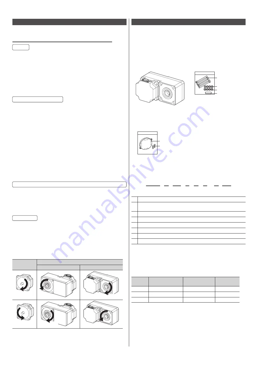
Package contents
Verify that the items listed below are included.
Report any missing or damaged items to the branch or sales office from which
you purchased the product.
Motor..................1 unit
Mounting screw
parallel key ....................1 set
①
③
②
④
①
Hexagonal socket
head screw: 4 pieces
② P
lain washer: 4 pieces
③
Spring washer: 4 pieces
④
Parallel key: 1 piece
Safety cover .......1 set
Operating Manual
(this document) .............1 copy
①
②
①
Safety cover: 1 piece
②
Mounting screw: 2 pieces
How to identify the product model
①
②
③ ④ ⑤ ⑥
⑦ ⑧
BLM 4 60 S H P - 5 FR
①
Motor type
BLM:
Brushless Motor
②
Frame size
2
: 60 mm (2.36 in.)
4
: 80 mm (3.15 in.)
5
: 90 mm (3.54 in.)
③
Output power
30
: 30 W
60
: 60 W
120
: 120 W
④
Motor classification
S
⑤
Motor connection method
H
: Connector type
⑥
Degree of protection
P
: IP65 (Motor: IP66 specification)
⑦
Gear ratio
Number: Gear ratio of gearhead
⑧
Gearhead type
FR
: Hollow shaft flat gearhead
FR
Gear
Model
Verify the model name of the purchased product against the model shown on
the package label. Check the motor model and the gearhead model against the
model name shown on their nameplates, respectively. Tell us the model name,
product serial number, and manufacturing date when you contact us.
The box (
) in the model name indicates a number representing the gear ratio.
Output
power
Model
Motor model
Gearhead
model
30 W
BLM230HP-
FR
BLM230HP-GFV
GFS2G
FR
60 W
BLM460SHP-
FR
BLM460SHP-GFV
GFS4G
FR
120 W
BLM5120HP-
FR
BLM5120HP-GFV
GFS5G
FR


