5
Note
•
Do not forcibly assemble the motor and gearhead. Also, prevent
metal objects or foreign substances from entering in the
gearhead. The pinion of the motor output shaft or gear may be
damaged, resulting in noise or shorter service life.
•
Do not allow dust to attach to the pilot sections of the motor and
gearhead. Also, assemble the motor and gearhead carefully by
not pinching the O-ring at the motor pilot section. If the O-ring is
crushed or severed, grease may leak from the gearhead.
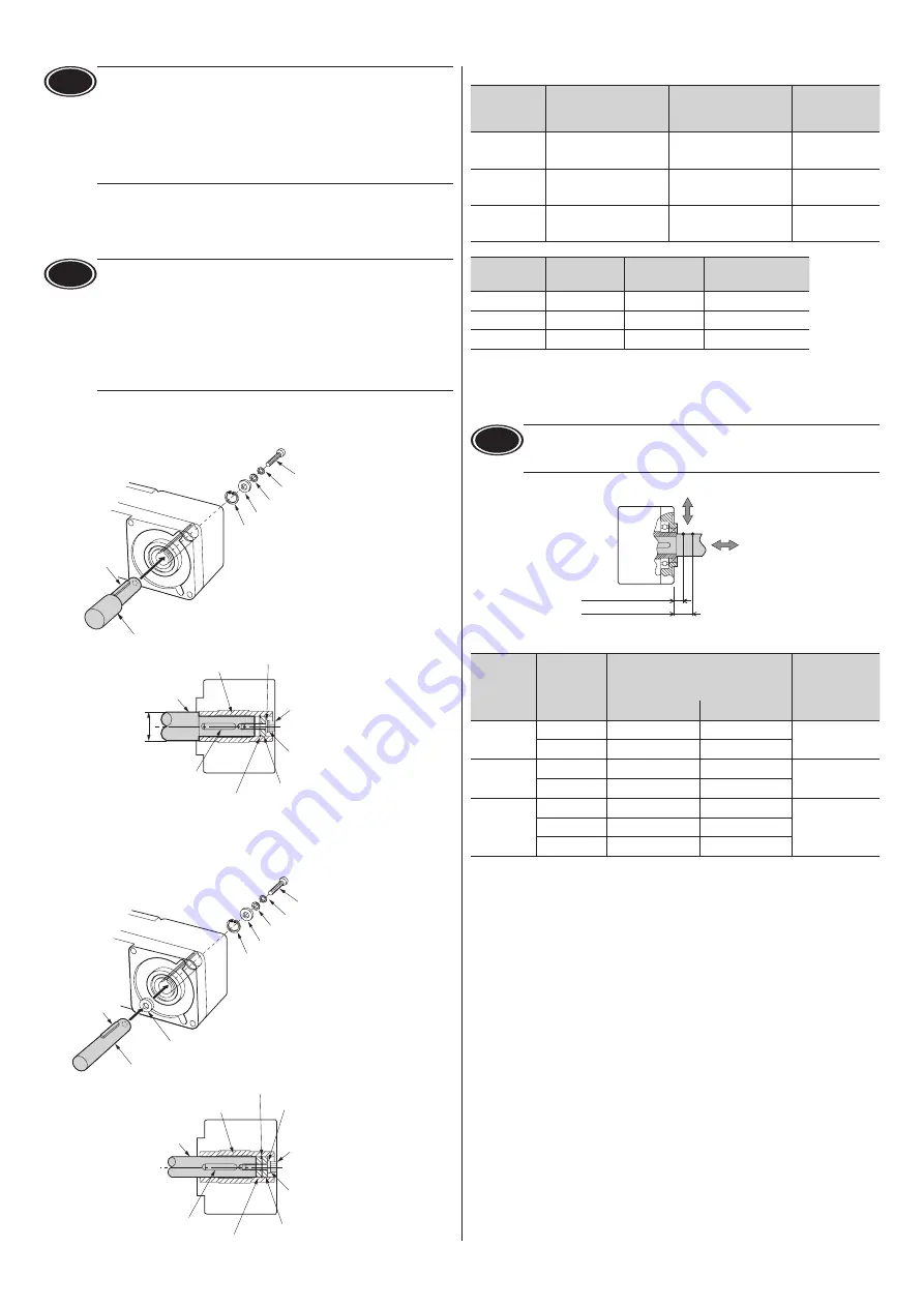
Installing a load
If a large impact occurs at instantaneous stop or a large radial load is applied,
secure a stepped load shaft.
Note
•
Apply grease (molybdenum disulfide grease, etc.) on the surface
of the load shaft and inner walls of the hollow output shaft to
prevent seizure.
•
When installing a load, do not damage the output shaft or
bearing. Forcibly inserting the load by driving it with a hammer
may damage the bearing. Do not apply any excessive force to the
output shaft.
•
Do not modify or machine the output shaft. This may damage
the bearing, resulting in damage to the motor and gearhead.
z
Stepped load shaft
Secure the retaining ring to the load shaft by tightening the hexagonal socket
head screw over a spacer, plain washer and spring washer.
Plain washer
Spacer
Retaining ring
Stepped load shaft
Parallel key
Spring washer
Hexagonal socket head screw
Retaining ring
Hollow output shaft
Hexagonal socket
head screw
Spring washer
Plain washer
Spacer
Parallel key
Load shaft
ØD
z
Non-stepped load shaft
Install a spacer on the load shaft side and secure the retaining ring to the load
shaft by tightening the hexagonal socket head screw over a spacer, flat washer
and spring washer.
Plain washer
Spacer
Retaining ring
Spring washer
Hexagonal socket head screw
Spacer
Stepped load shaft
Parallel key
Spacer
Retaining ring
Hollow output shaft
Hexagonalsocket
head screw
Spring washer
Plain washer
Spacer
Parallel key
Load shaft
Recommended load shaft installation dimensions [Unit: mm (in.)]
Output
power
Inner diameter of
hollow shaft (H8)
Recommended
diameter of load shaft
(h7)
Nominal
diameter of
retaining ring
30 W
Ø12
+0.027
0
(Ø0.4724
+0.0011
0
)
Ø12
0
-0.018
(Ø0.4724
0
-0.0007
)
Ø12 (Ø0.47)
60 W
Ø15
+0.027
0
(Ø0.5906
+0.0011
0
)
Ø15
0
-0.018
(Ø0.5906
0
-0.0007
)
Ø15 (Ø0.59)
120 W
Ø20
+0.033
0
(Ø0.7874)
+0.0013
0
Ø20
0
-0.021
(Ø0.7874)
0
-0.0008
Ø20 (Ø0.79)
Output
power
Applicable
screw
Spacer
thickness
Outer diameter of
stepped shaft (ØD)
30 W
M4
3 (0.12)
20 (0.79)
60 W
M5
4 (0.16)
25 (0.98)
120 W
M6
5 (0.20)
30 (1.18)
Permissible radial load and permissible axial load
Make sure a radial load and axial load applied to the output shaft will not exceed
the permissible values shown in the table below.
Note
Failure due to fatigue may occur when the bearings and output
shaft are subject to repeated loading by a radial or axial load that is
in excess of the permissible limit.
10 mm (0.39 in.)
20 mm (0.79 in.)
Distance from mounting surface
Axial load
Radial load
Output
power
Gear ratio
Permissible radial load [N (lb.)]
Distance from gearhead mounting
surface
Permissible
axial load
[N (lb.)]
10 mm (0.39 in.) 20 mm (0.79 in.)
30 W
5
,
10
450 (101)
370 (83)
200 (45)
15
to
200
500 (112)
400 (90)
60 W
5
,
10
800 (180)
660 (148)
400 (90)
15
to
200
1200 (270)
1000 (220)
120 W
5
,
10
900 (200)
770 (173)
500 (112)
15
,
20
1300 (290)
1110 (240)
30
to
200
1500 (330)
1280 (280)


