6
z
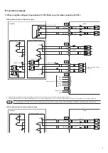
When using the voltage of input signals at 24 VDC
•
When pulse input is of open-collector type
Driver
1.5 to 2.2 kΩ
0.5 W or more
1.5 to 2.2 kΩ
0.5 W or more
1.5 to 2.2 kΩ
0.5 W or more
0 V
0 V
PLS (CW)
CN3
2
1
100 Ω
Twisted pair cable
Controller
100 Ω
100 Ω
100 Ω
2.2 kΩ
2.2 kΩ
2.2 kΩ
2.2 kΩ
1.5 to 2.2 kΩ
0.5 W or more
DIR (CCW)
4
3
24 VDC
R2
R2
R1
R1
R1
R1
24 VDC
R0
0 V
0 V
0 V
GND
24 VDC±10%
AWO
ALM
CN3
CN3
CN1
Motor lead wire
*1
5
4
3
2
1
10
9
R0
TIM
12
11
6
5
-
+
CN2
Current sink output circuit
Current source output circuit
470 Ω
1 kΩ
CS
8
7
470 Ω
1 kΩ
0 V
30 VDC or less
30 VDC or less
Output saturated
voltage
0.5 V max.
24 VDC
24 VDC
*2
1.5 to 2.2 kΩ
0.5 W or more
1.5 to 2.2 kΩ
0.5 W or more
10 mA or less
Red
Blue
Green
Black
Orange*2
*1 Connector pin assignments vary depending on the motor. For details, refer to "Connecting the motor" on p.4.
*2 This orange lead wire is for 5-phase stepping motor. For 2-phase stepping motor, do not connect anything to the pin No.3 since there is no orange lead wire.
y
The input voltage specification for the CW input and CCW input is 5 VDC. If the voltage exceeding 5 VDC is applied, connect an external resistor R1 so
that the input current becomes 7 to 20 mA.
Example) When the 24 VDC is connected: R1 = 1.5 to 2.2 kΩ, 0.5 W or more
y
The input voltage specification for the AWO input and CS input is 5 VDC. If the voltage exceeding 5 VDC is applied, connect an external resistor R2 so
that the input current becomes 5 to 15 mA.
Example) When the 24 VDC is connected: R2 = 1.5 to 2.2 kΩ, 0.5 W or more
y
Use output signals at 30 VDC, 10 mA or less. If the current exceeds 10 mA, connect an external resistor R0 so that the current becomes 10 mA or less.

