11
Smooth drive function
The smooth drive is a function to achieve lower vibration and noise at low
speeds operation without changing the step angle setting.
This function divides the step angle automatically in response to the pulse
signals. It is no need to change the setting of the pulse signals (speed, number
of pulses) on the controller side.
Set the smooth drive function with the OFF/SD switch.
Factory setting ON side (SD) [smooth drive function is enabled.]
Operating current
If the operating current rate is set with the RUN switch, the motor current for
when inputting pulses (operating current) can be changed.
If the load is small and there is an ample allowance for torque, motor
temperature rise can be suppressed by setting a lower operating current rate.
The operating current is a value in which the operating current rate is
multiplied by the rated current (100%).
Operating current = Motor rated current × Operating current rate
Factory setting F (operating current rate 100%)
RUN switch
Operating
current rate
RUN switch
Operating
current rate
0
25%
8
65%
1
30%
9
70%
2
35%
A
75%
3
40%
B
80%
4
45%
C
85%
5
50%
D
90%
6
55%
E
95%
7
60%
F
100%
Standstill current
When the motor stops, the current cutback function will be actuated to lower
the motor current to the standstill current.
The driver standstill current rate can be switched between 25% and 50%
using the STOP switch. When setting the switch to the OFF side, the standstill
current rate will be set to 25%. When setting the switch to the ON side, the
standstill current rate will be set to 50%.
The standstill current is a value in which the standstill current rate is
multiplied by the operating current.
Standstill current = Operating current set with the RUN switch × Standstill
current rate
Factory setting ON side (standstill current rate 50%)
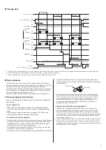
Pulse input
100 to 400 ms *
ON
OFF
Standstill current
Operating current
* The specific time varies depending on the load or operating pattern.
Command filter
The motor response corresponding to input pulses can be adjusted with the
OFF/FIL switch. When the switch is set to the ON side, starting/stopping of the
motor becomes smooth. Note, however, that synchronization performance in
response to the commands is decreased.
Set an appropriate value according to the specific load and purpose.
Factory setting OFF side (command filter is not used)
Command speed
Motor speed
• When the command
filter is not used
Command speed
Motor speed
• When the command
filter is used
5.5 ms
5.5 ms
Inspection
It is recommended that periodic inspections are conducted for the items
listed below after each operation of the motor. If an abnormal condition is
noted, discontinue any use and contact your nearest Oriental Motor sales
office.
During inspection
y
Are any of the mounting screws or connection parts of the driver loose?
y
Is there attachment of dust, etc., on the driver?
y
Are there any strange smells or appearances within the driver?
The driver uses semiconductor elements, so be extremely careful
when handling them. Static electricity may damage the driver.
Alarms
When the driver's protective function triggers and an alarm generates, the
ALM output is turned OFF and the motor current is cut off.
At the same time, the PWR/ALM LED will blink in red. The cause of the alarm
can be checked by counting the number of times the PWR/ALM LED blinks.
z
Alarm list
Number of
LED blinks
Alarm type
Cause and remedial action
2
Overheat
[Cause]
The temperature of the driver circuit board
reached 85 °C (185 °F).
[Remedial action]
Review the ventilation condition.
3
Overvoltage
[Cause]
A voltage exceeding the specification value
was applied.
[Remedial action]
Check the input voltage of the power supply.
[Cause]
A large inertial load was stopped abruptly.
Elevating drive of a large inertia load was
performed.
[Remedial action]
If this alarm generates during operation,
reduce the load or increase the acceleration/
deceleration.
5
Overcurrent
[Cause]
Excessive current was flowed through the
driver output circuit for motor.
[Remedial action]
Turn off the power and check that the motor,
cable and driver are not damaged.

