background image

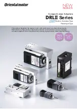
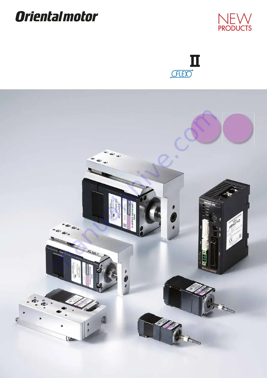
Compact Linear Actuators

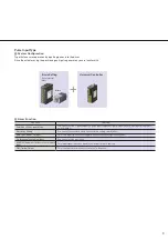
Built-In Controller Type

Pulse Input Type

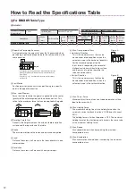
This product integrates the stepper motor with a ball screw to achieve linear motion.
Performance is improved by reducing the number of components such as couplings 
to make equipment more compact and by utilizing high-precision positioning technology.
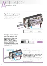
Repetitive 

Positioning 

Accuracy

±

0.003 

mm

Max. Thrust 

Force 

300 

N

DRL

 Series

Summary of Contents for DRL Series

Page 1: ...tepper motor with a ball screw to achieve linear motion Performance is improved by reducing the number of components such as couplings to make equipment more compact and by utilizing high precision po...

Page 2: ...em configuration flexibility Performance is improved by reducing the number of components such as couplings to make equipment more compact and by utilizing high precision positioning technology Compac...

Page 3: ...urs and Time Required for Design The compact body houses the entire linear motion mechanism The use of conventional internally produced parts is no longer required thus reducing the time for equipment...

Page 4: ...in order to directly receive the large thrust loads generated in linear motion Not necessary for the guide type and table type Actuator Features A stepper motor is used that stops immediately and wit...

Page 5: ...to Page 11 X Y table Focusing drive for a camera Use the electromagnetic brake type for vertical direction drive Spectrometer With Adjusting Knob Applications The X Y stage position can be finely adju...

Page 6: ...s reduced Example of Using PLC When using PLC you can build an operation system by connecting directly to an I O unit Because a positioning unit is not necessary on the PLC side space is saved and the...

Page 7: ...operating data The timer dwell time can be set 0 50 000 sec Setting Unit 0 001 sec Start Methods Operating Data Selection Method Starts the positioning operation when START is input after selecting M0...

Page 8: ...ownloaded from the Oriental Motor website Oriental Motor can also provide a CD ROM For details please contact the nearby Oriental Motor sales office PLS OUT Output Function Synchronous Operation Possi...

Page 9: ...he 1 pulse input or 2 pulse input negative logic mode with the pulse input mode select switch SW2 1 Resolution Setting You can set the resolution with the resolution setting switch SW1 AWO All winding...

Page 10: ...namic Permissible Moment N m Repetitive Positioning Accuracy mm Lost motion mm 10 20 30 40 100 110 120 50 100 150 200 250 300 Horizontal Vertical MP MY MR DRL20G 20 Ground 0 003 0 01 0 02 1 25 20 15 0...

Page 11: ...er Head X Y Stage Pin Lifter Adjusting a Mirror Positioning Device Vertical Operation of Probes Driving a Dispenser Driving a Pump Actuator Device Automatic Micro Plate Dispensing Fine Tuning of Senso...

Page 12: ...nt Support Point Traveling Parallelism Runout in the height between the actuator table installation surface and the top surface of the table Stroke The maximum distance the load can be pushed and pull...

Page 13: ...lculation 13 Product Number Code DRL 20 G 02 B 1 P N K D Series Name DRL DRL Series Frame Size 20 20 mm 28 28 mm 42 42 mm 60 60 mm Configuration Blank Standard Type G Guide Type V Table Type Stroke 02...

Page 14: ...example Other combinations are available 24 VDC Power Supply 2 Computer 1 2 To USB Port Installation plate Page 51 Connection cable Page 54 RS 485 communication cable Page 55 Accessory Sold separately...

Page 15: ...es Selection calculation 15 System Configuration Pulse Input Type An example of a single axis system configuration with the SCX11 controller is shown below Not supplied Universal Controller Controller...

Page 16: ...aft and joint Thrust force varies with load mass and acceleration 4 The maximum holding force at excitation is the value when the automatic current cutback function is ON Standstill Current 50 of the...

Page 17: ...temperatures above 10 C but no greater than 15 C Use a maximum speed of 12 mm s for the operating temperature range of 0 to 10 C for a high resolution stepper motor Note Use the actuator in condition...

Page 18: ...andard DRL42 04A8PN KD 40 8 Standard Adjusting Knob DRL42 04A8PM KD 40 8 Standard Electromagnetic Brake DRL42 10A2P KD 100 2 Standard DRL42 10A8P KD 100 8 Standard The following items are included in...

Page 19: ...Ball Screw Built In Controller Product Name Stroke mm Lead mm Motor Type Additional Function DRL60 05A4P KD 50 4 Standard DRL60 05A4PN KD 50 4 Standard Adjusting Knob DRL60 05A4PM KD 50 4 Standard El...

Page 20: ...0 3 0 06 20 1 28 23 0 3 28 23 0 3 16 5 58 1 5 10 4 0 5 0 22 0 021 h7 20 5 50 5 68 5 2 8 10 5 3 Effective stroke 30 Adjusting Knob Comes with a connection cable 0 6 m UL Style 3265 AWG24 DRL28 Product...

Page 21: ...K DRLM28 06B1P K 0 18 3 3 B B 6 2 4 M2 5 A A 5 1 A A 1 28 23 0 3 28 23 0 3 1 16 5 M3 B B 0 3 0 06 4 8 5 1 5 3 10 8 5 4 2 5 10 4 0 5 28 max 1 4 20 5 80 5 58 1 3 0 22 0 021 h7 4 Effective stroke 60 Come...

Page 22: ...L Style 3265 AWG26 20 60 Effective stroke 40 DRL42 Product Name Actuator Product Name Mass kg DRL42 04B2M K DRLM42 04B2M K 0 6 DRL42 04B2MN K DRLM42 04B2MN K 0 6 1 5 42 23 31 0 3 8 10 5 0 3 16 9 6 6 2...

Page 23: ...s 600 mm Comes with a connection cable 0 6 m UL Style 3265 AWG22 DRL60 Product Name Actuator Product Name Mass kg DRL60 05 4P K DRLM60 05 4P K 1 3 DRL60 05 4PN K DRLM60 05 4PN K 1 35 14 26 36 36 0 025...

Page 24: ...ame Mass kg DRL60 05 4PM K DRLM60 05 4PM K 1 7 A A 8 10 14 26 36 0 025 h7 0 1 5 40 98 1 138 2 50 0 3 12 60 5 5 10 4 4 M5 A A 50 0 3 60 M8 15 Deep 2 Electromagnetic Brake Leads 600 mm UL Style 1430 AWG...

Page 25: ...0 26 24 5 74 5 Effective stroke 50 M8 15 Deep Adjusting Knob Comes with a connection cable 0 6 m UL Style 3266 AWG22 DRL60 Product Name Actuator Product Name Mass kg DRL60 05B4MM K DRLM60 05B4MM K 1...

Page 26: ...tic current cutback function is ON Standstill Current 50 of the rated current The holding force is 0 when the power is OFF 5 Use the actuator at a maximum speed of 13 mm s for the operating temperatur...

Page 27: ...perature range of 0 to 10 C for a high resolution stepper motor Note Use the actuator in conditions where its surface temperature will be 90 C max The repetitive positioning accuracy is measured at a...

Page 28: ...Rolled Ball Screw Built In Controller Product Name Stroke mm Lead mm Motor Type Additional Function DRL42G 04A2P KD 40 2 Standard DRL42G 04A2PN KD 40 2 Standard Adjusting Knob DRL42G 04A2PM KD 40 2 St...

Page 29: ...he guide Repetitive positioning accuracy is measured on the linear guide If footnote or is not indicated then the accuracy values are identical MR MP MY Support Point Support Point Support Point Figur...

Page 30: ...K 0 27 DRL28G 03B1M K DRLM28G 03B1M K 0 26 DRL28G 03B1MN K DRLM28G 03B1MN K 0 27 6 2 4 M2 5 A A 3 1 5 A A 2 M2 5 32 5 1 5 5 8 8 1 10 4 0 5 5 55 8 0 5 18 0 3 12 0 3 28 23 0 3 12 R3 15 0 5 23 0 3 28 16...

Page 31: ...28 68 Effective stroke 40 4 M4 8 Deep 5 Motor Leads 600 mm UL Style 3265 AWG26 DRL42G Product Name Actuator Product Name Mass kg DRL42G 04 2PM K DRLM42G 04 2PM K 1 DRL42G 04A8PM K DRLM42G 04A8PM K 1...

Page 32: ...t Name Mass kg DRL42G 04B2MM K DRLM42G 04B2MM K 1 5 1 0 3 48 23 9 16 16 37 31 42 20 0 5 31 0 3 31 0 3 42 20 0 3 2 M4 119 2 86 1 3 43 111 82 0 5 24 0 3 19 0 3 R4 2 7 5 6 14 33 25 0 021 h7 0 UL Style 14...

Page 33: ...e 50 5 Motor Leads 600 mm UL Style 3266 AWG22 Adjusting Knob DRL60G Product Name Actuator Product Name Mass kg DRL60G 05 4PM K DRLM60G 05 4PM K 2 2 A A 4 M5 4 10 5 5 60 60 66 0 36 0 025 h7 50 0 3 27 A...

Page 34: ...t Name Mass kg DRL60G 05B4MM K DRLM60G 05B4MM K 2 2 11 5 10 1 5 131 3 53 24 9 0 5 12 1 5 A A 29 46 52 2 M5 66 27 R5 5 5 10 4 4 M5 A A 26 98 1 138 2 40 22 0 3 104 0 5 28 0 3 50 0 3 26 5 0 5 60 30 0 3 6...

Page 35: ...ternal force 3 The max thrust force is measured during constant speed operation in the horizontal direction with no load applied to the moving parts screw shaft and joint Thrust force varies with load...

Page 36: ...um speed of 24 mm s for temperatures above 15 C but no greater than 20 C Note Use the actuator in conditions where its surface temperature will be 90 C max The repetitive positioning accuracy is measu...

Page 37: ...8 55 1 10 5 8 10 25 17 9 39 5 0 3 17 9 7 14 0 5 8 10 0 3 67 4 0 3 4 0 014 0 014 20 0 3 20 0 3 39 5 0 3 2 6 7 20 24 5 0 5 20 13 8 7 5 5 0 3 5 0 5 51 3 45 9 11 21 5 0 5 13 3 5 7 0 3 4 5 17 35 0 3 8 65...

Page 38: ...8 Effective stroke 30 Adjusting Knob Installation Reference Surface 3 M3 6 Deep 2 M2 4 Deep 3 0 H8 6 Deep 3 0 H8 6 Deep 4 2 9 5 Counterbore 1 8 Deep 2 M3 6 Deep 6 M3 6 Deep Comes with a connection cab...

Page 39: ...ty is 50 Input Signal Input Mode Photocoupler Input Input Mode Photocoupler Input CW Pulse Signal Pulse signal CW Forward Direction Operation Command Pulse Signal Operation command pulse signal when i...

Page 40: ...LRD503 K LRD507 K LRD514 K Mass 0 12 kg 35 100 17 5 4 7 35 1 5 5 70 17 max 9 2 max Included Power Connector CN1 Connector MC1 5 3 STF 3 5 Phoenix Contact Actuator Connector CN2 Connector MC1 5 5 STF...

Page 41: ...Overvoltage Protection When the internal voltage of the driver exceeds the permissible value 7 LS Simultaneous Input When both LS and LS are detected LS Reverse Connection When the LS opposite from t...

Page 42: ...e CN2 Input A1 IN COM0 Input common A2 START Start Input A3 ALM RST Alarm Reset Input A4 AWO All Windings Off Input A5 STOP Stop Input A6 M0 Data Selection Input A7 M1 A8 M2 A9 M3 A10 M4 A11 M5 A12 HO...

Page 43: ...G22 0 3 mm2 to the driver s power connector CN1 Connecting the DC power supply input with the polarity reversed would damage the driver circuits Make sure that the polarity is correct before turning p...

Page 44: ...tance as short as possible Use 24 VDC for the input signals Using voltage exceeding the specifications can break elements Use 24 VDC max and current of 20 mA max for the output signals Using voltage e...

Page 45: ...or 20 mA max 24 VDC max 26C31 or Equivalent Notes Use the included cable with connector for the I O signal cable and keep the wiring distance as short as possible Use 24 VDC for the input signals Usin...

Page 46: ...upply indication Lights up when the power supply is input I O Signal Connector CN3 10 pins Indication Input output Pin No Code Signal Name CN3 Input 1 CW PLS CW Pulse Pulse 2 CW PLS 3 CCW DIR CCW Puls...

Page 47: ...2 A 50 0 00004 0 00008 0 00032 0 00016 B 80 0 000025 0 00005 0 0002 0 0001 C 100 0 00002 0 00004 0 00016 0 00008 D 125 0 000016 0 000032 0 000128 0 000064 E 200 0 00001 0 00002 0 00008 0 00004 F 250 0...

Page 48: ...correct before turning power on Provide a power supply that can supply adequate input current If the power supply capacity is inadequate abnormalities such as the following occur The actuator does not...

Page 49: ...n V0 is 24 VDC R1 1 5 to 2 2 k 0 5 W min Output Signal Check the specifications of the connected devices If the current exceeds 10 mA connect the external resistor R0 Use a twisted pair wire of AWG26...

Page 50: ...P KD DRLM28V 03A1P K LRD507 KD DRL28V 03A1PN KD DRLM28V 03A1PN K DRL28V 03B1P KD DRLM28V 03B1P K DRL28V 03B1PN KD DRLM28V 03B1PN K Pulse Input Product Line Product Name Actuator Product Name Driver Pr...

Page 51: ...0 03 2 M4 From the Back 6 5 Counterbore 3 5 Deep 2 M3 6 Deep 4 2 4 4 4 Counterbore 2 5 Deep PADRL 28 0 033 22H8 0 12 15 0 05 3 0 2 12 0 2 21 0 2 5 0 2 25 0 05 23 0 2 23 0 2 0 01 0 02 B A 0 01 30 5 40...

Page 52: ...ch as speed and I O monitoring and teaching Product Line Product Name OPX 2A Specifications Indication LED Cable Length 5 m Operating Ambient Temperature 0 to 40 C Non freezing Enlarged view Dimension...

Page 53: ...vice Pack 3 Microsoft Windows Vista Home Basic Service Pack 2 Microsoft Windows Vista Home Premium Service Pack 2 Microsoft Windows Vista Business Service Pack 2 Microsoft Windows Vista Ultimate Servi...

Page 54: ...mped for connecting connector coupled actuators They eliminate the need for assembling the lead wire and connector Connector coupled unit products come with a 0 6 m connection cable Product Line Produ...

Page 55: ...le the general purpose type with loose wire with a crimped terminal at one end which is appropriate for connecting to PLC panels and various other equipment and the dedicated type which is equipped wi...

Page 56: ...cation protocol You can use the network converter to control products supporting Oriental Motor s RS 485 in the host communication environment Product Line Network Type Product Name EtherCAT Compatibl...

Page 57: ...ipple P P 10 max Current Consumption 15 mA max Control Output NPN Transistor and Open Collector Output 30 VDC max 50 mA max Residual Voltage 0 7 V max for load current of 50 mA Indicator LED Detection...

Page 58: ...a transport mass of 5 kg vertically a traveling amount of 40 mm Check that the required specifications are within the product s specification values Check the graph of DRL42 positioning distance posit...

Page 59: ...15 10 5 0 1 6 1 4 1 2 1 0 0 8 0 6 0 4 0 2 0 Positioning Time s Positioning Distance mm DRL28 0 0 8 0 6 0 4 0 2 1 8 1 6 1 4 1 2 1 0 2 0 0 30 40 50 60 10 20 Positioning Distance mm Positioning Time s H...

Page 60: ...0 Fax 01 47 82 45 16 For more information please contact www orientalmotor de www oriental motor co uk www orientalmotor fr Printed in Germany Customer Center Support in German English 00800 22 55 66...

Reviews: