6 First time operation
−
46
−
6 First time operation
6.1 Starting
procedure
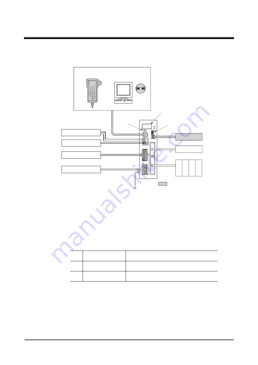
DC power supply
Motorized actuator
Main power supply
Emergency stop circuit
Battery
Host controller
Mode switch
Controller key
Pendant
switch
indicates an optional accessory
(sold separately).
or
Data editing software
EZED2
Teaching pendant
EZT1
Sensor
㪧㪜
∗
3
∗
1
∗
2
∗1
Absolute mode only.
∗2
Sensors are optional (sold separately) on the
EZS
Ⅱ
series and
ESR
series.
∗3
Not available on the
ESMC-K2
.
The following gives a brief explanation of the starting procedure from turning on the controller power to
actually operating the actuator.
1.
Wire each connector on the controller.
2.
Confirm that the motorized actuator model shown on the controller key is the same as the
model of the motorized actuator connected to the controller.
3.
Set the controller functions using the mode switches.
1 Mode
switching
ON: Driver mode
OFF: Controller mode
2
Pulse input mode
ON: 1-pulse input mode
OFF: 2-pulse input mode
3 ABS/INC
switching
ON: Absolute mode
OFF: Incremental mode
4.
To use a teaching pendant, turn the pendant switch ON.
5.
Turn on the main power and logic power supply to the controller.
Summary of Contents for EZ limo ESMC-A2
Page 92: ......


