2
Preparation
Checking the product
Upon opening the package, verify that the items listed below are
included. Report any missing or damaged items to the branch or
sales office from which you purchased the product.
•
Fan .............................................................................. 1 pc.
•
Power cable ................................................................ 1 pc.
•
Air Control Louver ..................................................... 1 pc.
•
Set of mounting screws for fan mounting .................. 1 set
(M5 Hexagonal socket head screws with captive washer,
Hexagonal nuts with flange 4 pcs. each)
•
Mounting screws for Air Control Louver (M5 Cross-recessed pan
head screws with captive washer) .............................. 4 pcs.
•
Operating manual (this manual) ................................. 1 copy
Checking the model name
To verify that the unit you’ve purchased is the correct one, check the
model number shown on the identification plate.
MBS18-BH
,
MBS18-BWH
,
MBS18-DH
,
MBS18-DWH
,
MBS18-TH
,
MBS18-TWH
,
MBS20-BH
,
MBS20-BWH
,
MBS20-DH
,
MBS20-DWH
,
MBS20-TH
,
MBS20-TWH
Installation
Location for installation
The fan is designed and manufactured for installation in equipment.
Install it in a well-ventilated location that provides easy access for
inspection. The location must also satisfy the following conditions:
•
Inside an enclosure that is installed indoors
•
Operating ambient temperature −10 to +60 °C (+14 to +140 °F)
(non-freezing)
•
Operating ambient humidity 85% or less (non-condensing)
•
Area that is free of explosive atmosphere or toxic gas (such as
sulfuric gas) or liquid
•
Area not exposed to direct sun
•
Area free of excessive amount of dust, iron particles or the like
•
Area not subject to splashing water (rains, water droplets), oil (oil
droplets) or other liquids
•
Area not subject to continuous vibration or excessive shocks
•
Area free of radioactive materials, magnetic fields or vacuum
•
Area free of excessive electromagnetic noise (from welders, power
machinery, etc.)
When using near a switching circuit or high-frequency power
supply, the induced current may flow inside the fan due to
electromagnetic noise (conductive noise, radiative noise). If the
induced current flows, the electric corrosion is caused in the
bearings of the fan. As a result, it may generate the noise or shorten
the service life of the products. Use the fan in the environment that
the electromagnetic noise does not cause.
How to install the fan
Install the fan onto an appropriate flat metal plate having excellent
vibration resistance and heat conductivity. Consider the weight of the
fan and install the fan in a location where sufficient strength can be
ensured.
Drill mounting holes in your equipment and affix the fan using the
supplied screws and the four mounting holes provided in the fan
casing.
Tightening torque: 1.2 N·m
z
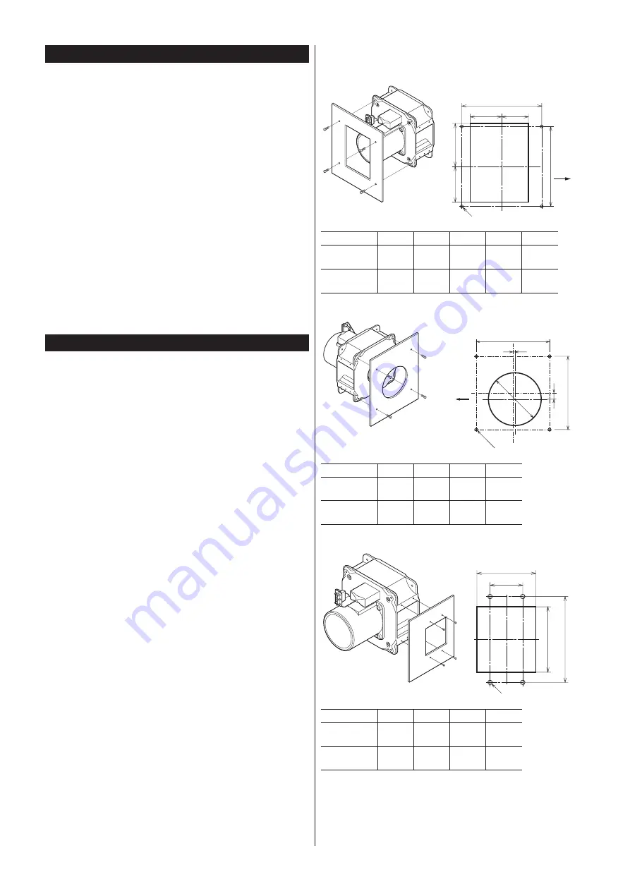
Installing method and installation dimensions
Motor side installation
Installation dimensions
[Unit: mm (in.)]
L2
L1
L4
4×Ø5.5 (Ø0.217)
L1
Outflow
L5
L3
Model
L1
L2
L3
L4
L5
MBS18-
152.7
(6.012)
60
(2.36)
51
(2.01)
82
(3.23)
68
(2.68)
MBS20-
166.9
(6.571)
59
(2.32)
52
(2.05)
92
(3.62)
68
(2.68)
Suction side installation
Installation dimensions
[Unit: mm (in.)]
L2
L1
L4
L1
L3
Outflow
4×Ø5.5 (Ø0.217)
Model
L1
L2
L3
L4
MBS18-
152.7
(6.012)
4
(0.17)
13
(0.52)
107
(4.21)
MBS20-
166.9
(6.571)
3.5
(0.14)
12.5
(0.49)
122
(4.8)
Exhaust side installation
Installation dimensions
[Unit: mm (in.)]
L2
L1
L4
L3
4×Ø5.5 (Ø0.217)
Model
L1
L2
L3
L4
MBS18-
105
(4.13)
72
(2.83)
80
(3.15)
40
(1.57)
MBS20-
120
(4.72)
72
(2.83)
92
(3.62)
40
(1.57)
Select mounting screws that are no more than 8 mm (0.315 in.)
longer than the thickness.


