

Checking the product
Verify that the items listed below are included. Report any missing
or
damaged items to the branch or sales office from which you purchased the
product.
Fan
Fan
kit
□
Fan
□
OPERATING MANUAL
(this document)
□
Fan
□
OPERATING MANUAL
(this document)
□
Finger guard
□
Mounting screws
How to identify the fan kit model
T- MDS1451-24L - G
G
: Finger guard
Mounting
screws
Fan model
Fan kit
Installation
Location for installation
The fan is designed and manufactured for installation in equipment.
Install it in a well-ventilated location that provides easy access for inspection.
The location must also satisfy the following conditions:
•
Inside an enclosure that is installed indoors
•
Operating ambient temperature
−
10 to +60 °C (+14 to +140 °F) (non-freezing)
•
Operating ambient humidity 85% or less (non-condensing)
•
Area that is free of explosive atmosphere or toxic gas (such as sulfuric gas)
or liquid
•
Area not exposed to direct sun
•
Area free of excessive amount of dust, iron particles or the like
•
Area not subject to splashing water (rains, water droplets), oil (oil
droplets) or other liquids
•
Area not subject to continuous vibration or excessive shocks
•
Area free of radioactive materials, magnetic fields or vacuum
•
Area free of excessive electromagnetic noise (from welders, power
machinery, etc.)
When using near a switching circuit or high-frequency power supply, the
induced current may flow inside the fan due to electromagnetic noise
(conductive noise, radiative noise). If the induced current flows, the
electric corrosion is caused in the bearings of the fan. As a result, it may
generate the noise or shorten the service life of the products. Use the fan in
the environment that the electromagnetic noise does not cause.
How to install the fan
Install the fan onto an appropriate flat metal plate having excellent vibration
resistance and heat conductivity. Drill holes on the mounting plate and fix the
fun on the plate using screws (not supplied).
Screw size: M4
Tightening torque: 0.6 N·m (5.3 lb-in)
For air orientation and rotational direction, see the indications shown on the
fan’s side frame.
Connecting the power supply
Connect the red wire to the positive
(+) power supply and the black wire
to the ground connection.
Check the voltage specification on
the product identification plate and
input the correct voltage.
Red
Black
DC power supply
GND
+
Connecting Protective Earth Terminal
(Only
MDS1451/ MDE1451
)
Ground the motor using the motors with a Protective Earth Terminal
.
Applicable crimp terminal:
Insulated round crimp terminal
Terminal screw size: M4
Tightening torque:
1.0 to 1.3 N·m (8.8 to 11.5 lb-in)
Applicable minimum lead wire size:
AWG18 (0.75 mm
2
) or more
Unit [mm (in.)]
Ø4.1 (0.16) min.
4.8 (0.19) max.
9.5 (0.37) max.
Connection of the alarm/sensor
Stall alarm, electronic alarm type
The orange or yellow wire is
lead wire for the alarm circuit.
GND is common to the sensor
and power supply.
If the fan stalls while the
power is on, an alarm signal
(H level) is output.
Orange
or
yellow
Black
Fan
Client's circuit
GND
27.6 VDC or less
∗
R
0 V
5 mA
or less
∗
㩷
MDS1451
,
MDE1451
= 30 VDC or less
Note
The stall alarm type of fan is not equipped with a delayed
trip-point alarm circuit. Therefore, an external delay function
is necessary to avoid the detection of fan start. The set time
of the delay function should be at least one second.
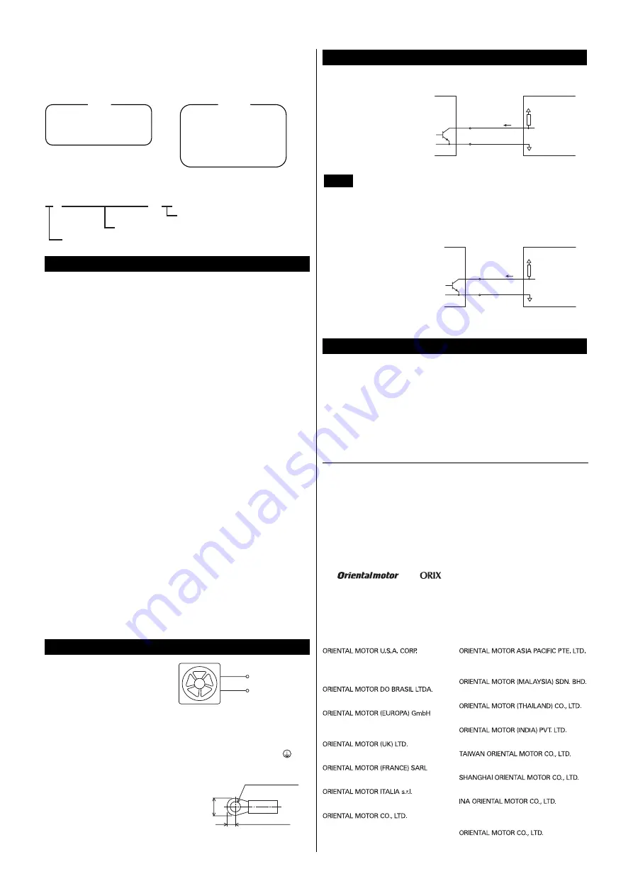
Pulse sensor type
The yellow wire is lead wire
for the pulse output. GND is
common to the sensor and
power supply.
Two cycles of rectangular
waves are output per rotation.
∗
㩷
MDS1751-24S
= 10 mA or less
Yellow
Black
Fan
Client's circuit
GND
30 VDC or less
R
0 V
5 mA
or less
∗
Overheat protection
The fan is equipped with an internal protective circuit against overheating. In
the event a lock-up condition is detected, this function automatically controls
the current flow to the fan motor’s windings, thus preventing the fan blades
from locking and burning out. The fan resumes operation automatically as
soon as it is released from the locked condition. Be sure to shut off the power
to the fan before performing an inspection.
•
Unauthorized reproduction or copying of all or part of this manual is
prohibited.
•
Oriental Motor shall not be liable whatsoever for any problems relating
to industrial property rights arising from use of any information, circuit,
equipment or device provided or referenced in this manual.
•
Characteristics, specifications and dimensions are subject to change
without notice.
•
While we make every effort to offer accurate information in the
manual, we welcome your input. Should you find unclear descriptions,
errors or omissions, please contact the nearest office.
•
and
are registered trademarks or trademarks
of Oriental Motor Co., Ltd., in Japan and other countries.
© Copyright
ORIENTAL MOTOR CO., LTD. 2012
Published in December 2017
Technical Support Tel:(800)468-3982
8:30
A.M.
to 5:00
P.M.
, P.S.T. (M-F)
7:30
A.M.
to 5:00
P.M.
, C.S.T. (M-F)
www.orientalmotor.com
Schiessstraße 44, 40549 Düsseldorf, Germany
Technical Support Tel:00 800/22 55 66 22
www.orientalmotor.de
Tel:01256-347090
www.oriental-motor.co.uk
Tel:01 47 86 97 50
www.orientalmotor.fr
Tel:02-93906346
www.orientalmotor.it
Tel:+55-11-3266-6018
www.orientalmotor.com.br
• Please contact your nearest Oriental Motor office for further information.
4-8-1Higashiueno,Taito-ku,Tokyo 110-8536
Japan
Tel:03-6744-0361
www.orientalmotor.co.jp
Tel:0800-060708
www.orientalmotor.com.tw
Singapore
Tel:1800-8420280
www.orientalmotor.com.sg
Tel:1800-806161
www.orientalmotor.com.my
Korea
Tel:080-777-2042
www.inaom.co.kr
Tel:1800-888-881
www.orientalmotor.co.th
Tel:400-820-6516
www.orientalmotor.com.cn
Tel:+91-80-41125586
www.orientalmotor.co.in
Hong Kong Branch
Tel:+852-2427-9800


