background image

19

Troubleshooting and remedial actions

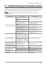
9  Troubleshooting and remedial actions

During motor operation, the motor or speed controller may fail to function properly due to an improper 

speed setting or wiring. When the motor cannot be operated correctly, refer to the contents provided in 

this section and take appropriate action. If the problem persists, contact your nearest office.

Note

Certain items must be checked with the power on. Be careful not to touch any live 
connections.

Phenomenon

Possible cause

Remedial action


The motor does not operate.


The speed doesn't change.

Both the FWD input and REV input 
are OFF.

Turn either FWD input or REV input 
ON.

Both the FWD input and REV input 
are ON.

The internal potentiometer or 
external potentiometer is not 
adjusted.

The factory setting is 0 r/min. Turn the 
potentiometer clockwise.

The INT/EXT input is ON when 
using the internal potentiometer.

Turn the INT/EXT input OFF.

The external potentiometer is not 
connected correctly.

Check the connection.

The INT/EXT input is OFF when 
using the external potentiometer.

Turn the INT/EXT input ON.

The motor or capacitor is not 
connected correctly.

Check the connection.

The motor speed does not 
change to the set speed.

The speed command voltage 
select switch (SW1-1) is being ON 
when the external potentiometer is 
used.

Turn the speed command voltage 
select switch (SW1-1) to OFF.

The speed command voltage 
select switch (SW1-1) is being ON 
when the speed command voltage 
is 0 to 5 VDC.

The motor is rotating at the 
maximum speed, while the 
speed cannot be changed.

The rate generator is not 
connected correctly.

Check the connection.


Motor operation is unstable.


Motor vibration is too great.

Effect of electrical noise.

See p.7 for measures with regard to 
noise.

The motor doesn't start 
instantaneously.

The acceleration time is too long.

Adjust the acceleration potentiometer.

Load inertia may be excessive.

Reduce the load inertia.

The motor doesn't stop 
instantaneously.

Load inertia may be excessive.

Increase the frictional load or reduce 
the load inertia.

Summary of Contents for MSC-1

Page 1: ...installation 6 4 2 Installation method 6 4 3 Installing an external potentiometer Sold separately 7 4 4 Installing and wiring in compliance with EMC Directive 7 5 Connection 9 5 1 Connection example...

Page 2: ...File No CE Marking UL 508 UL E91291 EN 50178 Conform to EN standards Low Voltage Directive EMC Directive Installation conditions EN Standard For use as a component within another device Overvoltage c...

Page 3: ...17 Internal potentiometer VR1 Sets the operating speed of the motor P 13 Acceleration time potentiometer VR2 Sets the acceleration time for the motor P 14 Deceleration time potentiometer VR3 Sets the...

Page 4: ...shock Do not forcibly bend pull or pinch the cable Doing so may cause fire or electric shock Do not touch the main circuit terminal of the speed controller immediately after the power is turned off fo...

Page 5: ...tion with an Oriental Motor s speed control motor equipped with an overheat protection device Failure to do so may result in fire Provide an emergency stop device or emergency stop circuit external to...

Page 6: ...from welders power machinery etc Area free of radioactive materials magnetic fields or vacuum Altitude Up to 1000 m 3300 ft above sea level Note If the ambient temperature of the speed controller exc...

Page 7: ...ts The installation wiring methods of the speed controller explained here represent the basic methods that are effective in helping your mechanical equipment conform to the EMC Directives The final le...

Page 8: ...ore of 7427122 W rth Elektronik GmbH Co KG ZCAT3035 1330 TDK Corporation or equivalent Install the ferrite core as close to the speed controller as possible Wiring the control cable Use a braided shie...

Page 9: ...he motor of World K Series and the motor is operated with relays switches and other contact switches To operate the motor be sure to connect control DC power supply A 60 W type motor or larger is equi...

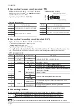
Page 10: ...ed cable when setting the rotation speed externally CN1 pin assignments Pin No Signal type Signal name Description 1 Control power supply 24 V Connect the 24 VDC for control circuit 2 0 V GND 3 Common...

Page 11: ...t breaker Fuse Speed command voltage Input circuit Output circuit Enclosure Shielded wire 24 VDC 10 100 mA or more 30 VDC or less 100 115 VAC or 200 230 VAC 1 2 9 10 24 V 4 7 k 24 V 0 V VM VL FWD REV...

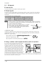
Page 12: ...ulses are output with each revolution of the motor output shaft synchronously with the motor operation pulse duty approx 50 The motor operating speed can be calculated by checking the SPEED OUT output...

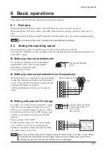
Page 13: ...he speed is set away from the speed controller connect the external potentiometer sold separately to CN1 When the INT EXT input is turned ON the external potentiometer is enabled Turn the potentiomete...

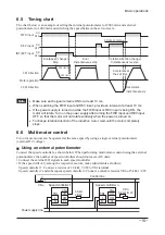
Page 14: ...art or when the speed is switched to the higher setting in a 2 speed operation Turning the acceleration time potentiometer VR2 clockwise increases the time Deceleration time Factory setting Min The de...

Page 15: ...nput and REV input OFF so that the motor will not rotate suddenly when the power is turned on To change rotation direction of the induction motor wait until the motor completely stops 6 6 Multi motor...

Page 16: ...lers is n Current capacity I 1 n mA Example If two speed controllers are used Current capacity I 1 2 mA current capacity I is calculated as 2 mA or more 6 7 Repeated cycle of operation instantaneous s...

Page 17: ...motor cable occurred disconnection or poor connection The capacitor was not connected or occurred poor connection Reduce the load Improve the operation condition such as the acceleration time or dece...

Page 18: ...if the thermal protector was closed the operation will not restart until the alarm is cleared by the ALARM RESET input 3 To restart the motor wait for at least 10 ms and then turn any of the input si...

Page 19: ...FF The external potentiometer is not connected correctly Check the connection The INT EXT input is OFF when using the external potentiometer Turn the INT EXT input ON The motor or capacitor is not con...

Page 20: ...by acknowledged The third party products mentioned in this manual are recommended products and references to their names shall not be construed as any form of performance guarantee Oriental Motor is n...

Reviews: