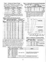
SETTING THE RUN AND STOP CURRENT LEVELS
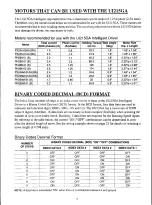
Motor
Total current
(Both phases) (A)
Phase current
(A/phase)
PX244-02AA (BA)
1.6
0.8
PX245-01AA (BA)
2.4
1.2
PH264-01(B)
2.2
1.1
PH266-01(B)
2.4
1.2
PH268-21(B)
2.5
1.25
PH296-02 (B)
2.5
1.25
PX244M-01M (BA)
2.4
1.2
PX245M-01AA (BA)
2.4
1.2
PH264M-31 (B)
1.7
0.85
PH265M-31 (B)
2.2
1.1
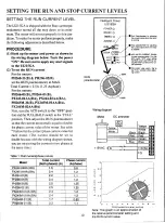
SETTING THE RUN CURRENT LEVEL
The UI215GA is shipped with the Run current po-
tentiometer turned all the way down to its mini-
mum. The motor will not run properly in this con-
dition. To make the motor perform properly, make
the following adjustments described below.
PROCEDURE
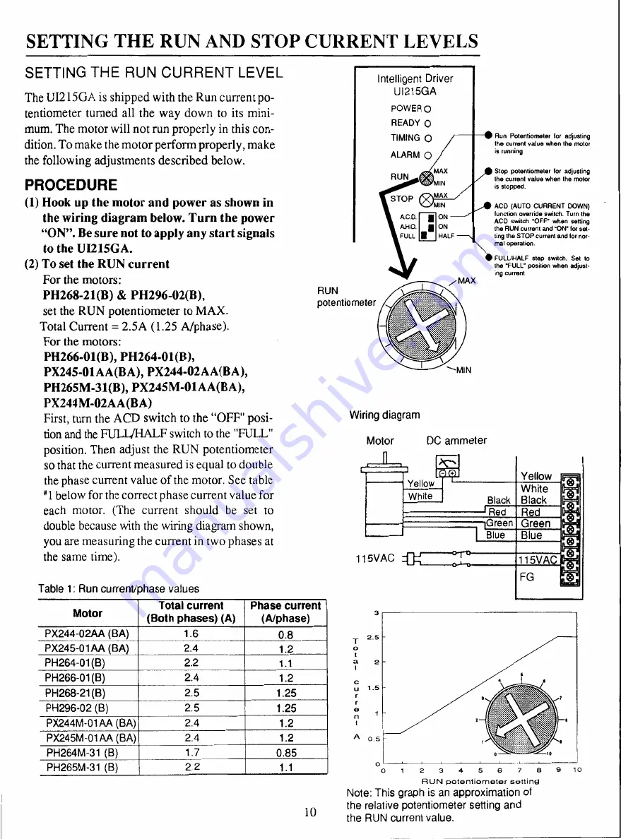
(1) Hook up the motor and power as shown in
the wiring diagram below. Turn the power
"ON". Be sure not to apply any start signals
to the U1215GA.
(2) To set the RUN current
For the motors:
PH268-21(B) & PH296-02(B),
set the RUN potentiometer to MAX.
Total Current = 2.5A (1.25 A/phase).
For the motors:
PH266-01(B), PH264-01(B),
PX245-01AA(BA), PX244-02AA(BA),
PH265M-31(B), PX245M-01AA(BA),
PX244M-02AA(BA)
First, turn the ACD switch to the "OFF" posi-
tion and the FULL/HALF switch to the "FULL"
position. Then adjust the RUN potentiometer
so that the current measured is equal to double
the phase current value of the motor. See table
"1 below for the correct phase current value for
each motor. (The current should be set t o
double because with the wiring diagram shown,
you are measuring the current in two phases at
the same time).
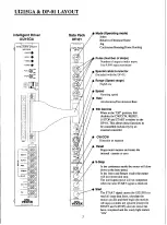
Table 1: Run current/phase values
RUN
potentiometer
10
Intelligent Driver
U1215GA
POWER 0
READY 0
TIMING 0
ALARM 0
RUN
STOP
AC.O.
AH.O.
FULL
Wiring diagram
MAX
MIN
MAX
ON
ON
HALF
Motor D C ammeter
Run Potentiometer for adjusting
the current value when the motor
is running
Stop potentiometer for adjusting
the current value when the motor
is stopped.
ACD (AUTO CURRENT DOWN)
function override switch. Turn the
ACD switch 'OFF` when setting
the RUN
current
and 'OW for set-
ting the STOP current and for nor-
mal operation.
FULUHALF step switch. Set to
the "FULL" position when adjust-
ing current
1
2
3
4
5
6
7
8
9
1 0
R U N p o t e n t i o m e t e r s e t t i n g
Note: This graph is an approximation of
the relative potentiometer setting and
the RUN current value.


