EXTERNAL CONTROL OF THE UI215GA
The UI215GA can be controlled by an external source such as a Programmable Controller, binary coded
decimal (BCD) thumbwheel switches, other dry contact switches or open-collector transistor switches.
All of the motion data; starting speed, running speed, acceleration/deceleration rate, direction, length of
travel and the operating mode can be set by simply turning "ON" one or any combination of the inputs
on CN I to perform the desired motion. An input is considered to be "ON" when there is a connection
made between ground (Pin #31) and the desired input line. A signal that is "ON" will have a voltage level
of approximately OVDC, while a signal that is "OFF" will have a voltage level of approximately 10VDC.
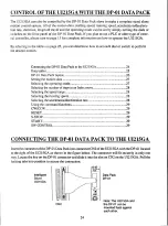
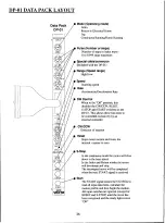
If you plan to use the DP-01 Data Pack to control the UI215GA, please turn to page 24 for complete
information on how to operate the UI215GA.
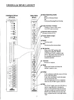
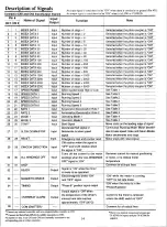
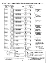
Referring to the table on page 14 which describes the input/ouput signals on CN1 and CN2, input lines
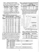
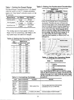
1-16 are used to set the number of steps in an index move. The speed range is selected on input line *17.
Input lines 18 - 21 are used to set the running speed of the move. The acceleration/deceleration rate is
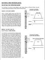
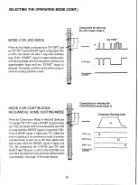
set by using input lines #22 and #23. The operating mode input lines are #24 and #25. The "START" signal
input line is pin #26. Pin #27 is the decelerate/halt input line. Pin #28 is the "RESET" signal input. Pin
#29 is used for the direction of rotation input (CW/CCW). Pin #30 is used for the "ALL WINDINGS
OFF" input signal. The common ground for all of the input lines (1 - 30) is located on pin #31.
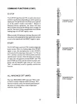
Also referring to page 10, pins #32 to #36 on CN I are used as outputs to the external controller. Pin #32
is the "READY" signal output. Pin #33 is the "MAGNETIC BRAKE" signal output. The timing signal
is located at pin #34 while pin #35 represents the "OVERHEAT ALARM" signal output. Pin #36 is the
common emitter transistor type output for lines #32 to *35.
By referring to tables 1 thru 4 on page 15, you can determine which inputs are necessary (turned "ON")
to perform the desired motion.
Description of signals1
4
Data tables1
5
Wiring the UI215GA to a programmable controller1
6
Setting the motion data1
7
Selecting the operating mode1
7
Home hunting with the UI215GA and a PLC1
9
Improving the accuracy of the home position2
0
Selecting the number of steps in an index move2
1
Selecting the speed range2
1
Selecting the running speed2
1
Selecting the acceleration/deceleration rate2
2
Using the command functions2
2
CW/CCW2
2
RESET2
2
S -STOP2
3
START2
3
All windings off (AWO)2
3
13

