CONTROL OF THE UI215GA WITH THE DP-01 DATA PACK
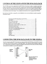
Connecting the DP-01 Data Pack to the UI215GA
24
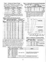
Data tables
25
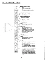
DP-01 Data Pack layout
26
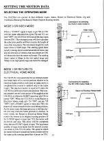
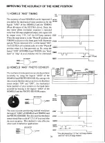
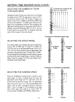
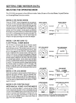
Setting the motion data
27
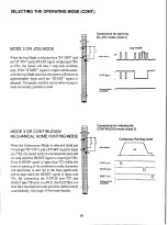
Selecting the operating mode
27
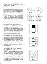
Selecting the number of steps in an Index move
28
Selecting the speed range
28
Selecting the running speed
28
Selecting the acceleration/deceleration rate
28
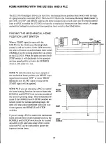
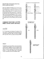
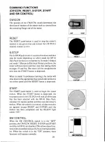
Using the command functions
29
CW/CCW
29
RESET
29
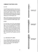
S-STOP
29
START
29
SW CONTROL
29
The UI215GA can also be controlled by the DP-01 Data Pack alone to make a complete stand alone
motion control system. All of the motion data; starting speed, running speed, acceleration/decelera-
tion rate, direction, length of travel and the operating mode can be set by simply turning the dials or
switches on the front panel of the DP-01 Data Pack. If you plan to use a PLC or other type of exter-
nal controller, please turn to page 13 for complete information on how to operate the UI215GA.
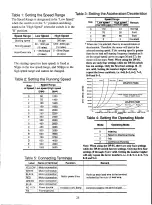
By referring to the tables on page 25, you can determine how to set each dial or switch to perform
the desired motion.
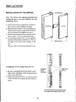
CONNECTING THE DP-01 DATA PACK TO THE UI215GA
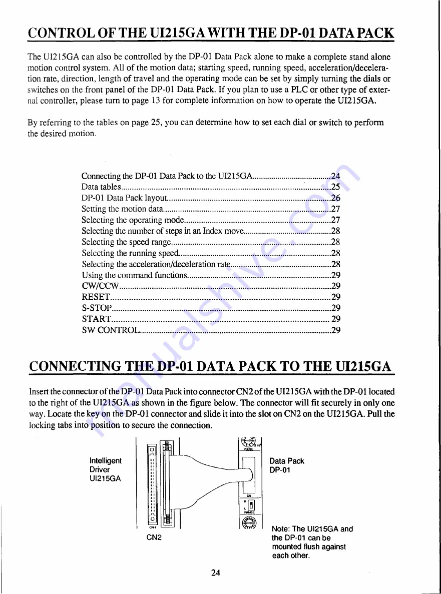
Insert the connector of the DP-01 Data Pack into connector CN2 of the UI215GA with the DP-01 located
to the right of the UI215GA as shown in the figure below. The connector will fit securely in only one
way. Locate the key on the DP-01 connector and slide it into the slot on CN2 on the UI215GA. Pull the
locking tabs into position to secure the connection.
Intelligent
Driver
UI215GA
CN2
Data Pack
DP-01
Note: The UI215GA and
the DP-01 can be
mounted flush against
each other.
24

