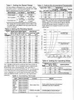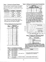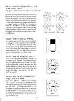
Table 1: Setting the Speed Range T a b l e 3: Setting the Acceleration/Deceleration
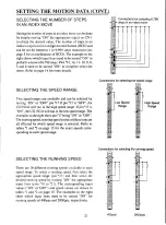
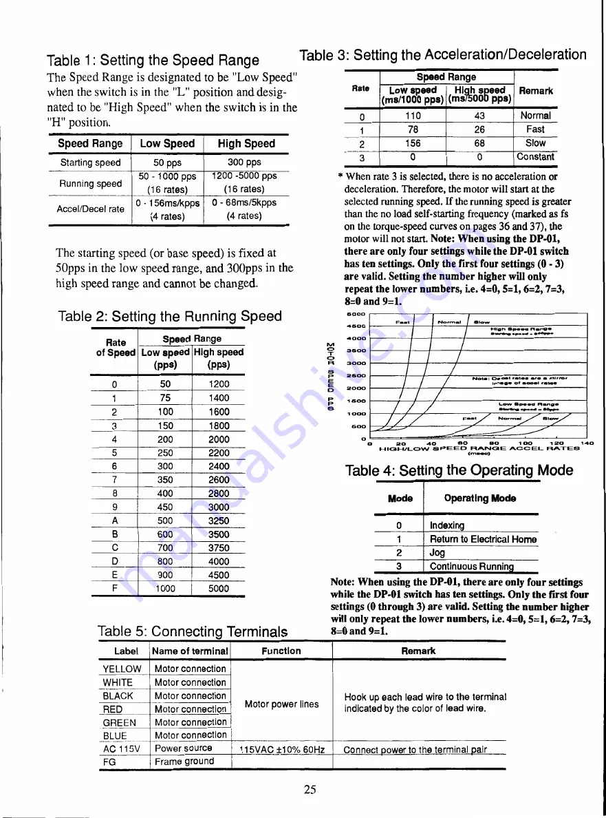
The Speed Range is designated to be "Low Speed"
when the switch is in the "L" position and desig-
nated to be "High Speed" when the switch is in the
"H" position.
Speed Range
Low Speed
High Speed
Starting speed
50 pps
300 pps
Running speed
50 - 1000 pps
(16 rates)
1200 -5000 pps
(16 rates)
Accel/Decel rate
0 - 156ms/kpps
(4 rates)
0 - 68ms/5kpps
(4 rates)
Rate
of Speed
Speed Range
Low speed
(pps)
High speed
(pps)
0
50
1200
1
75
1400
2
100
1600
3
150
1800
4
200
2000
5
250
2200
6
300
2400
7
350
2600
8
400
2800
9
450
3000
A
500
3250
B
600
3500
C
700
3750
D
800
4000
E
900
4500
F
1000
5000
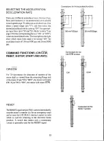
Rate
Speed Range
Remark
Low speed
(ms/1000 pps)
High speed
(m575000 pps)
0
110
43
Normal
1
78
26
Fast
2
156
68
Slow
3
0
0
Constant
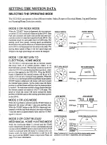
Mode
Operating Mode
0
Indexing
1
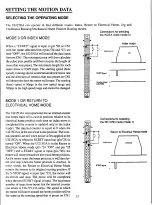
Return to Electrical Home
2
Jog
3
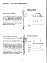
Continuous
Runnin•
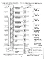
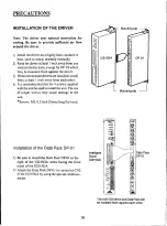
Table 5: Connecting Terminals
8 = 0 and 9=1.
Label
Name of terminal
Function
Remark
YELLOW
Motor connection
Motor power lines
Hook up each lead wire to the terminal
indicated by the color of lead wire.
WHITE
Motor connection
BLACK
Motor connection
RED
Motor connection
GREEN
Motor connection
BLUE
Motor connection
AC 115V
Power source
115VAC ±10% 60Hz
Connect power to the terminal pair
FG
Frame ground
The starting speed (or base speed) is fixed at
50pps in the low speed range, and 300pps in the
high speed range and cannot be changed.
Table 2: Setting the Running Speed
0117
O
M
M
1
0
104?
* When rate 3 is selected, there is no acceleration or
deceleration. Therefore, the motor will start at the
selected running speed. If the running speed is greater
than the no load self-starting frequency (marked as fs
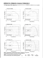
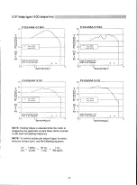
on the torque-speed curves on pages 36
and
37), the
motor will not start. Note: When using the DP-01,
there are only four settings while the DP-01 switch
has ten settings. Only the first four settings (0 - 3)
are valid. Setting the number higher will only
repeat the lower numbers, i.e. 4=0, 5=1, 6=2, 7=3,
8=0 and 9=1.
6 0 0 0
4 5 0 0
4 0 0 0
3 5 0 0
3 0 0 0
2 6 0 0
2 0 0 0
1 6 0 0
1 0 0 0
6 0 0
0
F a m t
N
o
r
m
a
l
S l o w
I-11g 1•1 S p e e d M a n g .
o u r * ,
O
H
M
.
.
N o t . : O a c m o l r a n t . . m r 0 t r o t
1 m a g i o f m o o . ' r a t e .
w
Table 4: Setting the Operating Mode
Note: When using the DP-01, there are only four settings
while the DP-01 switch has ten settings. Only the first four
settings (0 through 3) are valid. Setting the number higher
will only repeat the lower numbers, i.e. 4=0, 5=1, 6=2, 7=3,
25

