background image

MOTORS THAT CAN BE USED WITH THE UI215GA

Motor

Total current

(Both phases) (A)

Phase current

(A/phase)

Holding Torque

(oz-in)

Step Angle

(deg)

Motor Size

Dia. x Length

PX244-02AA (BA)

1.6

0.8

22.2

1.8°

1.65" x 1.54"

PX245-01AA (BA)

2.4

1.2

31.9

1.8°

1.65" x 1.85"

PH264-01 (B)

2.2

1.1

40.3

1.8°

2.22"0 x 1.54"

PH266-01 (B)

2.4

1.2

83.3

1.8°

2.22"0 x 2.13"

PH268-21 (B)

2.5

1.25

125

1.8°

2.22"0 x 2.99"

PH296-02 (B)

2.5

1.25

174

1.8°

3.27"0 x 2.44"

PX244M-01AA (BA)

2.4

1.2

16.6

0.9°

1.65" x 1.54"

PX245M-01AA(BA)

2.4

1.2

23.6

0.9°

1.65" x 1.85"

PH264M-31 (B)

1.7

0.85

25

0.9°

2.22"0 x 1.54"

PH265M-31 (B)

2.2

1.1

52.8

0.9°

2.22"0 x 2.01"

NUMBER

OF STEPS

BINARY CODED DECIMAL (BCD) "ON"/"OFF" COMBINATIONS

INDEX DATA 8

INDEX DATA 4

INDEX DATA 2

INDEX DATA 1

0

OFF

OFF

OFF

OFF

1

OFF

OFF

OFF

ON

2

OFF

OFF

ON

OFF

3

OFF

OFF

ON

ON

4

OFF

ON

OFF

OFF

5

OFF

ON

OFF

ON

6

OFF

ON

ON

OFF

7

OFF

ON

ON

ON

8

ON

OFF

OFF

OFF

9

ON

OFF

OFF

ON

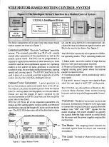
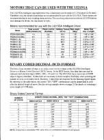
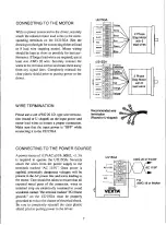
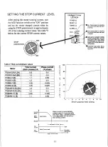
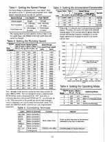
The UI215GA intelligent step motor driver has a maximum current output of 1.25A/phase (2.5A total).
Therefore, only the motors listed below are recommended for use with the UI215GA. These motors are
recommended due to their winding characteristics. The use of any other motors with the UI215GA driver
may damage the driver, the step motor or both.

Motors recommended for use with the UI215GA Intelligent Driver

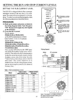
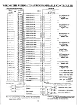
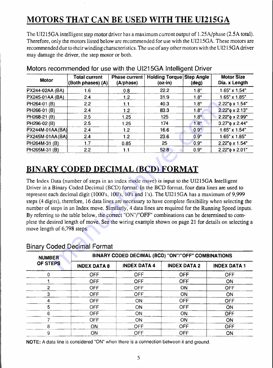
BINARY CODED DECIMAL (BCD) FORMAT

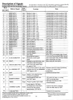
The Index Data (number of steps in an index mode move) is input to the UI215GA Intelligent

Driver in a Binary Coded Decimal (BCD) format. In the BCD format, four data lines are used to
represent each decimal digit (1000's, 100's, 10's and l's). The UI215GA has a maximum of 9,999
steps (4 digits), therefore, 16 data lines are necessary to have complete flexibility when selecting the
number of steps in an Index move. Similarly, 4 data lines are required for the Running Speed inputs.
By referring to the table below, the correct "ON"/"OFF" combinations can be determined to com-

plete the desired length of move. See the wiring example shown on page 21 for details on selecting a
move length of 6,798 steps.

Binary Coded Decimal Format

NOTE: A data line is considered "ON" when there is a connection between it and ground.

5

Summary of Contents for SUPER VEXTA DP-01

Page 1: ...underutilized and idle equipment along with credit for buybacks and trade ins Custom engineering so your equipment works exactly as you specify Critical and expedited services Leasing Rentals Demos I...

Page 2: ...VEXTA OPERATOR S MANUAL MODELU1215GA INTELLIGENT STEP MOTOR DRIVER MODEL DP 01 DATA PACK O R I E N T A L O R I E N T A L MOTOR A r v I c 3 s T R 9 1 Manual Number M91UI215GA 3...

Page 3: ...chanical dimensions 38 Specifications 40 Oriental Motor s reputation for award winning quality and cost effective products is well known among original equipment manufacturers Our Vexta and Super Vext...

Page 4: ...mode Return to electrical home mode Continuous running mode Scan and Jog mode one step ata time With the use of a Programmable Controller the UI215GA can also execute a Hunt for mechanical home and o...

Page 5: ...ofile Constant Running Speed Starting Speed Slope Accel T1 T 2 Slope t Decel Increasing D e c r e a s i n g Pulse P u l s e Frequency F r e q u e n c y Pulse C o n s t a n t Pulse F r e q u e n c y TD...

Page 6: ...celeration Rate SW Control Wheninthe Off position this disablesthe CW CCW RESET S STOPandSTARTswitchesonthe DP 01 Thisallowsthesefunctionsto becontrolledexclusivelybyan externalcontroller CW CCW Direc...

Page 7: ...nnector Case H o n d a Tsushin Kogyo Co Ltd Screw Driver for 1 p c External Controller Connector Case Strain Relief for 2 sets 6 pieces total External Controller Connector Mounting Bracket A 2 p c Fla...

Page 8: ...2 5A total Therefore only the motors listed below are recommended for use with the UI215GA These motors are recommended due to their winding characteristics Theuse of any other motors with the UI215G...

Page 9: ...hole drilling dimensions Rear and front Mounting Pattern 10 04 1 0 6 3 Side Mounting The UI215GA should be mounted to a metal surface in order to be properly heat sulked Please allow lin of freespaceb...

Page 10: ...A YELLOW WHITE BLACK RED GREEN B L U E UI215GA YELLOW WHITE BLACK RED GREEN B L U E Yellow White Black VVhiteiOrang Recommendedwire termination Round or U shaped CONNECTING TO THE POWER SOURCE A power...

Page 11: ...l holding torque is still required to hold the load when the motor is at rest e g motor is moving aweight against the force of a spring or gravity SETTING THE FULUHALF STEP FUNCTION SWITCH When the FU...

Page 12: ...Current to the motor will not be shut off however If anoverheat alarm occurs review the application requirements to make sure that they are within the specifications of the UI215GA Drive duty cycle am...

Page 13: ...st turn the ACD switch to the OFF posi tion andthe FULL HALF switch to the FULL position Then adjust the RUN potentiometer sothat the current measured is equal to double thephase current value of the...

Page 14: ...peed Base Speed Stopped Run Current Stop Current P e r C e n 100 80 0 6 0 r U n 4 0 C U r 2 0 e n Intelligent Driver U1215GA POWER 0 READY 0 TIMING 0 ALARM 0 AC D Al LO FULL MIN ON ON HALF Run Potenti...

Page 15: ...panel to the appropriate positions to achieve the desired motion An exter nal controller is not required in this configuration Seepage 24 for more details 3 Parallel Control Both the DP 01 Data Pack a...

Page 16: ...celeration rate is setby using input lines 22and 23 The operating mode input lines are 24and 25 The START signal input line is pin 26 Pin 27 is the decelerate halt input line Pin 28 is the RESET signa...

Page 17: ...ration Deceleration Rate 1 See Table 3 23 23 RATE 2 Input Acceleration Deceleration Rate 2 See Table 3 24 24 MODE1 Input Operating Mode 1 See Table 4 25 25 MODE 2 Input Operation Mode 2 See Table 4 26...

Page 18: ...REEN Motor connection BLUE Motor connection AC 115V Power source 115VAC 10 60Hz Connect power to the terminal pair FG Frame ground The Speed Range is designated to be Low Speed when the switch is in t...

Page 19: ...O P R E S E T C W C C W A L L W I N D I N G S O F F G R O U N D 2 3 3 0 R E A D Y 31 T I M I N G 3 2 BCD input lines for the l s digit Negative logic BCD input lines for the 10 s digit Negative logic...

Page 20: ...en the UI215GA is in the electrical home position The inter nal counter isset to0when power is first applied to the UI215GA or when the RESET input line pin 28 is turned ON When the UI215GA is in the...

Page 21: ...00 00 00 told to stop when the RESET signal is input pin 00 28 By connecting the S STOP pin 27 and 00 RESET pin 28 pins to a PLC the UI215GA can hunt for amechanical home position limit switch 00 00...

Page 22: ...the UI215GA When the table activates the S STOP switch it will decelerate to the appropri atebase speed until it activates the HOMELS where it will come to a rest NOTE 1 After the table has been stopp...

Page 23: ...logical AND of HOMELS and TIMING any dead band or slop in your switches will be eliminated A N D F U N C T I O N 2 HOMELS AND PHOTO SENSOR The mechanical home position can alsobesetmore accurately by...

Page 24: ...run in the low speed range The examples to the right show pin 17 being ON or OFF The starting speed running speedand accel decel rate are all effected by which speed range is selected Refer to tables...

Page 25: ...haft as viewed from the mounting flange end of the motor If pin 29 is OFF the motor will rotate CW If pin 29 is ON the motor will rotate CCW RESET The RESET input line pin 28 is used to immediately st...

Page 26: ...pin 26 is used to begin the motor motion When the leading edge of the START signal is seen the microprocessor in the UI215GA will read all of the data input lines pins 1 to 30 on CN 1 and then calcula...

Page 27: ...ting mode can be set by simply turning the dials or switches on the front panel of the DP 01 Data Pack If you plan to use a PLC or other type of exter nal controller please turn to page 13 for complet...

Page 28: ...ion GREEN Motor connection BLUE Motor connection AC 115V Power source 115VAC 10 60Hz Connect power to the terminal pair FG Frame ground The starting speed or base speed is fixed at 50pps in the low sp...

Page 29: ...DP 01 This allows these functions to becontrolled exclusively by an external controller CW CCW Direction of rotation Reset Stops motor motion andresetsthe internal counter to zero S Stop In the contin...

Page 30: ...e motor nears the home position it will decelerateandstopwhenthehomeposition isreached The maximumnumber ofstepsfrom homethat the internal counter can return is 16 777 216 steps The speed at which the...

Page 31: ...ffected by which speed range is selected Refer to tables 1 and 2 on page 25 for the exact speeds corresponding to each speed range SELECTING THE RUNNING SPEED There are16 different running speeds avai...

Page 32: ...n is depressed When in mode 3 continuous running the motor will slow down to the appropriate basespeedand continue to run at that speed until the RESET button is depressed START The START push button...

Page 33: ...all them at least 1 inch away from each other 4 It is recommended that the 4 screws supplied with the unit beused to install the unit The use of longer screws may cause damage to the unit Screws M3 0...

Page 34: ...emperature over 130 C Is the duty cycle too high Is the ambient temperature too high Is the motor heat sinked well enough Is the Run current level set too high Is the Stop current level set too high H...

Page 35: ...If the DP 01 Data Pack is controlling the UI215GA Is the SW CONTROL switch in the OFF position Is the correct data being set If an external controller is controlling the U1215GA Are the controllers o...

Page 36: ...r a move with a preset length that utilizes the S STOP function Motion does not occur until the leading edge of a START signal is seen i 40 2ms or longer START S STOP READY H L L H L MAGNETIC BRAKE L...

Page 37: ...he electrical home point For the U1215GA to return succesfully to the electrical home point the maximum distance from the electrical home point is 16 777 215 steps Timing for the Jog Mode Mode 2 This...

Page 38: ...ning 0 2ms or longer START S STOP RESET READY MAGNETIC BRAKE H L H L H L L H L 0 2ms ms VR MOTION E I VS MOTOR p D 20ms 170ms At 70ms VR Running Speed VS Starting Speed Timing for the Data Inputs This...

Page 39: ...r e n t 2 2 A With D 20 D a m p e r 00 01 60 40 20 0 1 1 S p e e d K p p s P H 2 6 8 2 1 B PX245 01 B A 10 0 0 1 0 1 1 S p e e d K p p s P H 2 6 6 0 1 B 10 1 0 F U L L S T E P H A L F S T E P To t a...

Page 40: ...E P H A L F S T E P Total C u r r e n t 2 2 A With D 2 0 D a m p e r t s 1 0 NOTE Holding torque is reduced while the motor is stopped by the automatic current down ACD function fs No load self starti...

Page 41: ...et 2 14DIA 03 5 Countersink 26DIA 06 6 Female Connector for CN1 PCA 36FES Honda Tsushln Kogyo Co Ltd Solder type 2 49 63 2 1L 3 2 M 2 metric size tap N r 1 doIt I 11 4 41 1 I 2 17 55 2 Case for Female...

Page 42: ...Shalt Type 08 2 6LEAD 7 3 185 LONG MIN 161 2AWG24 L_ 1 65 42 I2216 4 3 1 t 1 PH26 Orype Unit inch mm e 5 25 r A 7 i _ _ e 8 1 1 6 _ T PI 9I 4 N bo 1 N L N r i 1 Double ShaftType 6 6 58_ LEADS A r56 4...

Page 43: ...5 on connector CN1 Switch selectable override available Timing Signal Phase 0 output The step motor phase excitation sequence is repeated every four full steps eight half steps When the step motor is...

Page 44: ...RANGE Pulse Speed Running Speed 16 levels 0 F for each speed range 32 total SPEED AcceVDecel Rate Acceleration Deceleration Rate 4 0 3 for each speed range 8total RATE SW Control Disables CW CCW RESET...

Page 45: ...tructions for installation operation and maintenance and c The Products or Parts have not been subjected to misuse negligence accident or unauthorized repairs THE FOREGOING WARRANTY IS IN LIEU OF ANY...

Page 46: ...uipment Have surplus equipment taking up shelf space We ll give it a new home Learn more Visit us at artisantg com for more info on price quotes drivers technical specifications manuals and documentat...

Reviews: