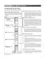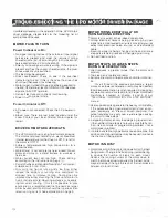
UPD DRIVER SWITCH SETTINGS
The UPO driver has been designed lo be easily readjust
ed lo meet a wide variety of application requiremen
t
s
.
SWITCH SELECTABLE FUNCTIONS:
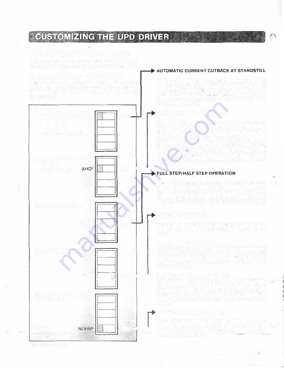
The UPO driver can be set up lo match a wide range of
system requirements by using the dip switches as shown
1n
figure 7
The functions controlled by the dip
switches are:
Figure 7
• AUTOMATIC CURRENT
CUTBACK AT
ACD*
STANDSTILL
(ACD·Aulo current down)
• AUTOMATIC THERMAL
CUTOUT
(AHO·Auto heat of�
9
FULL STEP/HALF STEP
OFF
OFF --1.....---1
*FULL
'f
f
l
�"----
HALF
0
INPUT SIGNAL METHOD
ct
DRIVER SELF TEST
FUNCTION
2P
I
')
1 P* ___ __.
1---t.,;;�
TEST__..
_
__,
•standard settings
11
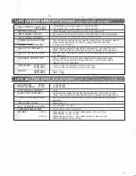
After the motor has been stopped for approximately 1 00
milliseconds, the motor current is automatically reduced
to between 13% to 100% of the selected running current.
This reduces driver and motor power consumption dur
ing stopped periods in applications where holding
torque is not required.
AUTOMATIC THERMAL CUTOUT
When the driver's internal temperature reaches 8
0
°
C.
power lo the motor is automatically removed. In appli
cations wt1ere the sudden removal ol drive current could
pose a safety problem (e.g. motor is moving a weight
against the force of a spring or gravity), the A.H.0. switch
can be used to disable this automatic power off function
The overheat warning indicator will light and the signal
will be sent to the 0.HEAT terminal if the temperature
exceeds 80
°
even with the automatic power off lune
lion disabled.
This switch selects either the four-phase-on full step, or
the four-five phase on half step mode. In the full step posi
tion. a 500 step per revolution motor will move 0.72
degrees for each pulse received, and will move 0.36
degrees for each signal if the half step mode is selected.
INPUT SIGNAL METHOD
The two input signals that control step motor direction
and movement are swllch selectable in two configura
tions:
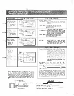
1 PULSE-STEP AND DIRECTION
The direction input signal being held high or low causes
the motor lo rotate CW or CCW when pulses are received
at the step terminal. Care must be taken so step signal is
inactive when the direction signal is changed. or missed
steps may result.
2 PULSE-UP-CLOCK OOWN-�LOCK
The motor will rotate one step in one pirection
w
h
e
1
pulses are sent to the firs1 terminal, and will rotate onf.
step in the other direction when a signal is received at the
second terminals. Again, care must be take:1 that both
inputs are not active at the same time, or missed steps will
result
DRIVER SELF TEST FUNCTION
When !be switch is in the "TEST' position, the driver's
internal pulse generator is activated and the motor will
-.
move at 3pps. This is used to checking the driver and the
motor wiring coriiiections.

