background image

t.i;t•PXUl11=t•X•iiJ:Gii=il

11

:f:IU•ik•);1•l;JW3;•:[;t3Eii

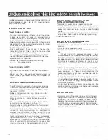
If problems develop in the opera11on of the  UPD  motor/ 

driver  package.  please  refer  10  the  following  list  of 

symptoms and causes

MOTOR  FAILS TO TURN 
Power  Indicator is  On: 

o

No signal coming to driver. Check lo see if inpul signal

pulses  are  present  and  meet  the  required  timing

characteristics. (5V, <25ma. length> 5  microsecond,

pulse rise/fall time < 2 microsecond).

o

Polarity or input signal pulse is  wrong 

If 

the signal  ,s

present  and has the correct charac1erist1cs. the  plus/

minus wires may be switched.

o

The load may  be jammed

o

Driver  overheated.  Check  to  see  if  the  overheat

indicator light is on  If this is the case, the driver has

shut down because of overheating

o

Motor current turned off by a signal being applied to

the AW. OFF terminal. (All WINDINGS OFF.) Remove

signal at A.W,  OFF terminal.

o

Run self test function to check for miswiring.

o Driver in wrong  Input mode.

Power Indicator is  Off: 

o AC power not connected. Check  the  AC power wir­

ing.

o Blown  fuse.  There  are  two  fuses  located  under  the

cover.  Contact  your  local  Oriental  Motor  dealer 

tor

repair.

DRIVER  OR MOTOR  OVERHEATS 

o

The U PD motor/driver is a high performance device.

The motor and driver normally run  warm. Maximum

internal temperature for the driver is 80

° 

C., and 

tor

the motor is  130

° 

C.

o

Ambient  Temperature  too  high.  Move  motor  10  a

cooler location.

o

Motor/Driver is  not  sufficiently  heal  sinked.  Mount

motor  and drive  to  a  metal  surface  to  work  as  a

heat sink.

o

Motor  currenl  level  set  too  high.  Check  selling

according to  the instructions on page  12.

o

Current Cutback at Standstill Overriden. Turn current

cutback switch  (A.C.D.) on. 

o

Duty 

cycle 

too  high  or  running  time  too  long  Either

reduce  the  amount  of  running  lime  compared  to

stopped 

t

i

me

or  improve  cooling  Cooling  can  be

improved by either  mounting the  driver and  motor to 

heat conductive metal mounting surfaces, or by apply­

ing  forced air  cooling.  II lh1s  1s  not possible  in  your

application, II is recommended thal the next size larger

motor be used. and ltie 

motor 

should be run at less than

rated running current. See explanation on page 9.

13 

MOTOR TURNS ERRATICALLY OR 

TURNS WRONG  DIRECTION 

o

Motor is mis-wired, or has loose connections.

o

Strong  electrical  noise  1s  being  picked  up  by  input

signal Imes.  Use twisted pair wires. move Input wires

away  from  electrical  noise  source.  or  use  shielded

cable

.

o

01rec11on signal is being changed at the same time a

step pulse is being rece

i

ved

Change signal tim

i

ng

_

o

Run 

self 

test function.

MOTOR STOPS OR  LOSES STEPS 

DURING ACCELERATION: 

o

Load  requires  a  greater  torque  than  the  motor  can

produce

o

Too steep an acceleration ramp.

o

Extreme mis-match of load inertia and motor rotor iner­

lta.

For  all  three  of  the  previous  problems,  a  larger 

motor, or a slower acceleration ramp may be needed. 

(Some experimentation is often required in designing 

acceleration ramps for step motors.) Proper motor load 

matching  is  covered  in  chapter  4  and  5  of  our 

"TECHNICAL  INFORMATION  ON  STEP  MOTORS" 

manual. 

o

User-supplied pulse generator frequency 

is 

not stable

If the pulses are being generated directly from a corn­

puler,  especially  an  interrupt  driven  computer,  the

pulse frequency  may vary  over a wide range causing

the molor to loose steps.

o

A stepping motor can only lose steps in groups of  ten.

If the number of lost steps is not evenly divisible by ten,

lhen it is a controller or programming problem - not a

motor/driver problem.

o

In certain unstable, high performance applications, the

add11ton of a magnet damper may be needed to reduce

the chance of losing steps.

MOTOR IS NOISY 

o

Motor/driver combination is too powerful for the 

toad

being driven. Change to half stepping (remembering

to  double  the  number  of  steps  for  each  move).

Reduce  the  running  current  of  the  motor  down  to

match the torque actually require(/ by the load. Add a

magnet damper. Change the ratio of the transmission

between motor and load.

,... ,  

Summary of Contents for Super Vexta UP0566-NBA

Page 1: ...HAFT DOUBLE SHAFT U D564 NAA UPD564 NBA UPD566 NM UP0566 NBA UPD569 NM UP0569 NBA UPD596H NAA UP0596 NBA UPD599H NM UPD599H NBA UPD5913H NAA UP05913H NBA STEP ANGLE 0 12 072 0 72 0 72 072 0 72 HOLDING...

Page 2: ...ONIC MOTION CONTROL SYSTEMS 3 MOTION CONTROL USING THE UPD STEP MOTOR DRIVER PACKAGE 4 INPUT SIGNAL CHARACTERISTICS 4 NEW PENTAGON 5 PHASE DRIVER FEATURES 5 KEYS TO THE 5 PHASE MOTOR S EXCELLENCE 5 6...

Page 3: ...matic current cutback atstandstill reduces power consumption 10 13 to 100 when motor 1s not moving Automatic thermal cutout circuitry protects driver lrom damage from overheating Chopper lrequency of...

Page 4: ...ction signals The step signal turns on and off for each step the motor is to takP and l H direction output 1s held high or low depend ing on the d1recl1on CW E 8Wt rne motor s to move See Figure 2 3 C...

Page 5: ...the step motor The input pulse waveform is shown in Figure 4 A logical ON or HIGH is 4 5 volts and LOW is be1ween 0 0 5 volts The inputpulseshould haveTIL timing characteris tics i e the pulse rise a...

Page 6: ...dif ference is speclacular Because the Five Phase design has an additional pair of magnetic poles it runs substan tially smoother wilh no noticeable vibration from resonances As a comparison for examp...

Page 7: ...1 0 STEPS 10 o s 1tP tC 100 Xseai J 1oms d v v s_c a191 0 2 t JL 200gcm TL 50gcm 2 PHASE TORQUE RIPPLE S PHASE TORQUE RIPPLE 1 72 I Torque Ripple 29 Torque Ripple 5 72 BASIC CHARACTERISTICS E excellen...

Page 8: ...erminal and one step counter clockwise for each pulse detected at the CW CCW terminal NORM TEST When the switch is in the lest position the drivefs internal pulse generator is activated and the motor...

Page 9: ...causes the motor to rotate clockwise 2 PULSE MOOE Motor moves one step counicr clockwlse for eacn puls detected Motor moves on the tra long edge of the pulse A W OFF ALL WINDINGS OFF A signal applied...

Page 10: ...nr 51 curren1 cutl acx 12 10 t1w u e or loss Duty Cycle _T_ _ x 100 50 T1 T2 1 Driver InternalCircuit I L ____ _____ _J 2SC1815 or Equivalent Actual duty cycle limil will depend on the load heat sink...

Page 11: ...isstill active Precautions should be takenloreset the system and protect persons and property against unexpected motor activity The UPD driver is NOT U L Listed The UPO motor driver should be used on...

Page 12: ...automatic power off function The overheat warning indicator will light and the signal will be sent to the 0 HEAT terminal if the temperature exceeds 80 even with the automatic power off lune lion disa...

Page 13: ...ing to figure 8c the automatic current cutback level can be set to 13 to 100 of the selected running current as 1nd1cated in the STOP SCALE table The STOP current level should be set lo the minimum va...

Page 14: ...eat conductive metal mounting surfaces or by apply ing forced air cooling II lh1s 1s not possible in your application II is recommended thal the next size larger motor be used and ltiemotorshould be r...

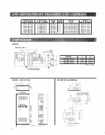
Page 15: ...ERHEAT PROTECTION OUTPUT CURRENT IS SHUT OFF AND OVERHEAT INDICATOR LIGHTS WHEN INTERNAL HEAT SINK TEMPERATURE EXCEEDS 80 C SWITCH SELECTABLE CURRENT SHUT OFF OVERRIDE DIMENSIONS UDX5114NA 1 6 W x 4 2...

Page 16: ...R UDX5114NA t o I A I o VEXTA o 8 g I Ot SHAFT TYPE SINGLE DOUBLE SINGLE DOUBLE SINGLE DOUBLE LEAD DRIVER DRIVER WIRES TYPE MODEL NUMBER 5 5 NEW PENTAGON UDX5114NA 5 5 NEW PENTAGON UDX5114NA 5 5 NEW P...

Page 17: ...IVER UOX5107N Unit in o 39 a I I o 59 0 39 0 59 1 3 94 15 SHAFT LEAD TYPE WIRES SINGLE 5 DOUBLE 5 SINGLE 5 DOUBLE 5 SINGLE 5 DOUBLE 5 DRIVER DRIVER TYPE MODEL NUMBER 5 NEW PENTAGON UDX5107N 5 NEW PENT...

Page 18: ...ll Yf uo l J El o Tf SHAFT TYPE SINGLE DOUBLE SINGLE DOUBLE SINGLE DOUBLE LEAD DRIVER DRIVER WIRES TYPE MODEL NUMBER 5 5 J NEW PENTAGON UDX5114NA 5 5 J NEW PENTAGON UDX5114NA 5 5 J NEW PENTAGON UOX511...

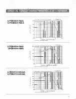
Page 19: ...uency r r r Full Step 4o Ex 100 SOO 115VAC 60HZ 2 8A PHASE W D 40 DAMPER a tep o H If S 4 EX 400 T 0 R Q 300 E 0 200 z l N 100 III1111 PULLOUT TORQUE J i r I I I r 0 01 0 1 t 10 100 SPEED x 1O TEPS SE...

Page 20: ...l SLEADS 23 6LENGTH ui siyie 3266 AWG22 SECTION AA r 335 en DRIVER UDX5128NA A i 0 1 tt t tr r2 NO 4 J tlfliC ij ij QJJ VEXTA 1 1 1 2 74 t lhlUIU LEAD DRIVER DRIVER WIRES TYPE MODEL NUMBER 5 5 NEW PEN...

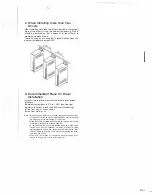
Page 21: ...densing Free from dust or corrosive gas Free from water or oil Note When auach ng the driver In a close space such as control box o somewhere close to a hea1 rad atong object vent hole should be make...

Page 22: ...1 0 0 01 I l 0 1 1 10 100 SPEED x 1000 STEPS SEC fs rna imum no load starting heqvency 100 115VAC 60HZ 1 4A PHASE W 0 200AMPER Full Slep 4o Ex Half Step 4 50 Ex PULLOUT TORQUE 8 60 40 20 0 0 01 K 0 1...

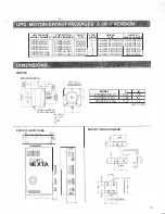
Page 23: ...599H NBA PH599H NBA DOUBLE 5 5 NEW PENTAGON UOX5128NA UP05913H NAA PH5913H NAA SINGLE 5 5 NEW PENTAGON UDX5128NA UPD5913H NBA PH5913H NBA DOUBLE 5 5 NEW PENTAGON UDX5128NA o IMEN s o N s i _ t 1 0 I I...

Reviews: