background image

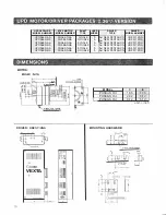
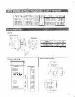
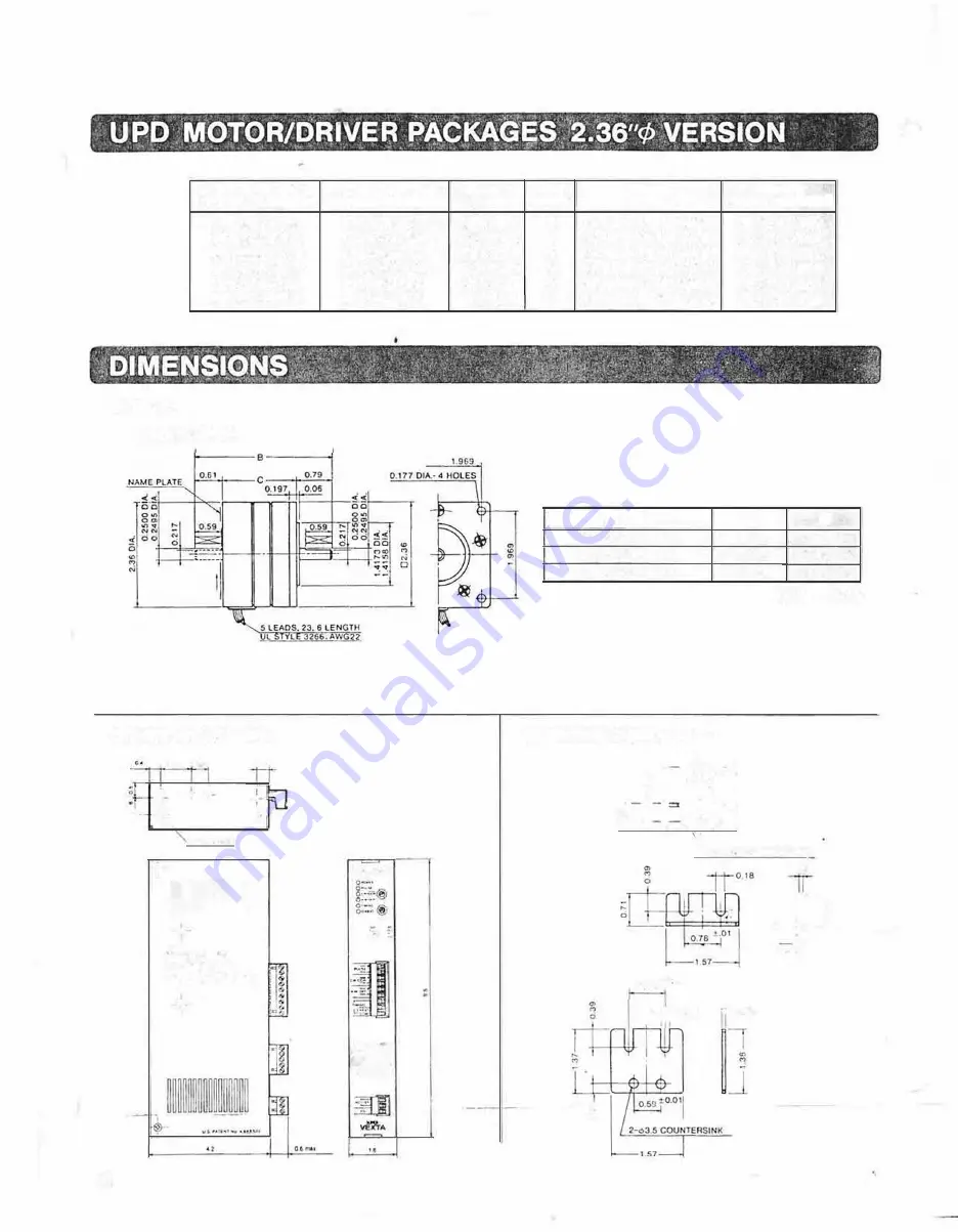
UPD PACKAGE 

MODEL NUMBER 

UPD564-NAA 

UPD564-NBA 

UP0566-NAA 

UPD566-NBA 

UPD569-NAA 

UPD569-NBA 

MOTOR: 

PH560-NDA 

DRIVER:  UDX5114NA 

"

.. 

..

-o-l 

-• 

0 .... 

-+ 

� 

�• •O\.I'<. 

� 

��ijij00������00�� 

© 

O�u.1:� 

VEXTA 

15 

STEP MOTOR 

MODEL  NUMBER 

PH564-NAA 

PH564-NBA 

PH566-NAA 

PH566-NBA 

PH569-NAA 

PH569-NBA 

lllt<l 

.. 

5( 

Qlll.,Yf• 

uo.,., • ..,� 

-

l:;J

· 

·-El 

·o··

-

�Tf. 

SHAFT 

TYPE 

SINGLE 

DOUBLE 

SINGLE 

DOUBLE 

SINGLE 

DOUBLE 

LEAD 

DRIVER 

DRIVER 

WIRES 

TYPE 

MODEL NUMBER 

5<J, NEW PENTAGON 

UDX5114NA 

5<J, NEW PENTAGON 

UDX5114NA 

5<J,  NEW PENTAGON 

UOX5114NA 

5<J, NEW PENTAGON 

UDX5114NA 

5<J,  NEW PENTAGON 

UDX5114NA 

5<J, NEW PENTAGON 

UDX5114NA 

MODEL 

PH564-N DA 

1.65 

3.05 

PH566-N DA 

2.32 

3.72 

PH569-N DA 

3.72 

5.12 

unit= inch 

MOUNTING  HARDWARE: 

.. 

�1 

f i f �f 

7--,3 5 COUNTCRSINK 

=:001 

0 78 

-;r-018 

-006 

0.08 

�J� 

Io s� l 

Summary of Contents for Super Vexta UP0566-NBA

Page 1: ...HAFT DOUBLE SHAFT U D564 NAA UPD564 NBA UPD566 NM UP0566 NBA UPD569 NM UP0569 NBA UPD596H NAA UP0596 NBA UPD599H NM UPD599H NBA UPD5913H NAA UP05913H NBA STEP ANGLE 0 12 072 0 72 0 72 072 0 72 HOLDING...

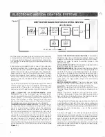
Page 2: ...ONIC MOTION CONTROL SYSTEMS 3 MOTION CONTROL USING THE UPD STEP MOTOR DRIVER PACKAGE 4 INPUT SIGNAL CHARACTERISTICS 4 NEW PENTAGON 5 PHASE DRIVER FEATURES 5 KEYS TO THE 5 PHASE MOTOR S EXCELLENCE 5 6...

Page 3: ...matic current cutback atstandstill reduces power consumption 10 13 to 100 when motor 1s not moving Automatic thermal cutout circuitry protects driver lrom damage from overheating Chopper lrequency of...

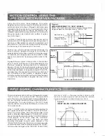
Page 4: ...ction signals The step signal turns on and off for each step the motor is to takP and l H direction output 1s held high or low depend ing on the d1recl1on CW E 8Wt rne motor s to move See Figure 2 3 C...

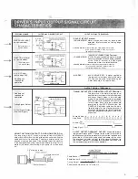
Page 5: ...the step motor The input pulse waveform is shown in Figure 4 A logical ON or HIGH is 4 5 volts and LOW is be1ween 0 0 5 volts The inputpulseshould haveTIL timing characteris tics i e the pulse rise a...

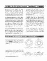
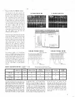
Page 6: ...dif ference is speclacular Because the Five Phase design has an additional pair of magnetic poles it runs substan tially smoother wilh no noticeable vibration from resonances As a comparison for examp...

Page 7: ...1 0 STEPS 10 o s 1tP tC 100 Xseai J 1oms d v v s_c a191 0 2 t JL 200gcm TL 50gcm 2 PHASE TORQUE RIPPLE S PHASE TORQUE RIPPLE 1 72 I Torque Ripple 29 Torque Ripple 5 72 BASIC CHARACTERISTICS E excellen...

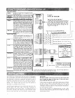
Page 8: ...erminal and one step counter clockwise for each pulse detected at the CW CCW terminal NORM TEST When the switch is in the lest position the drivefs internal pulse generator is activated and the motor...

Page 9: ...causes the motor to rotate clockwise 2 PULSE MOOE Motor moves one step counicr clockwlse for eacn puls detected Motor moves on the tra long edge of the pulse A W OFF ALL WINDINGS OFF A signal applied...

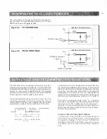
Page 10: ...nr 51 curren1 cutl acx 12 10 t1w u e or loss Duty Cycle _T_ _ x 100 50 T1 T2 1 Driver InternalCircuit I L ____ _____ _J 2SC1815 or Equivalent Actual duty cycle limil will depend on the load heat sink...

Page 11: ...isstill active Precautions should be takenloreset the system and protect persons and property against unexpected motor activity The UPD driver is NOT U L Listed The UPO motor driver should be used on...

Page 12: ...automatic power off function The overheat warning indicator will light and the signal will be sent to the 0 HEAT terminal if the temperature exceeds 80 even with the automatic power off lune lion disa...

Page 13: ...ing to figure 8c the automatic current cutback level can be set to 13 to 100 of the selected running current as 1nd1cated in the STOP SCALE table The STOP current level should be set lo the minimum va...

Page 14: ...eat conductive metal mounting surfaces or by apply ing forced air cooling II lh1s 1s not possible in your application II is recommended thal the next size larger motor be used and ltiemotorshould be r...

Page 15: ...ERHEAT PROTECTION OUTPUT CURRENT IS SHUT OFF AND OVERHEAT INDICATOR LIGHTS WHEN INTERNAL HEAT SINK TEMPERATURE EXCEEDS 80 C SWITCH SELECTABLE CURRENT SHUT OFF OVERRIDE DIMENSIONS UDX5114NA 1 6 W x 4 2...

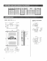
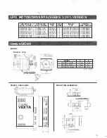
Page 16: ...R UDX5114NA t o I A I o VEXTA o 8 g I Ot SHAFT TYPE SINGLE DOUBLE SINGLE DOUBLE SINGLE DOUBLE LEAD DRIVER DRIVER WIRES TYPE MODEL NUMBER 5 5 NEW PENTAGON UDX5114NA 5 5 NEW PENTAGON UDX5114NA 5 5 NEW P...

Page 17: ...IVER UOX5107N Unit in o 39 a I I o 59 0 39 0 59 1 3 94 15 SHAFT LEAD TYPE WIRES SINGLE 5 DOUBLE 5 SINGLE 5 DOUBLE 5 SINGLE 5 DOUBLE 5 DRIVER DRIVER TYPE MODEL NUMBER 5 NEW PENTAGON UDX5107N 5 NEW PENT...

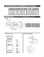
Page 18: ...ll Yf uo l J El o Tf SHAFT TYPE SINGLE DOUBLE SINGLE DOUBLE SINGLE DOUBLE LEAD DRIVER DRIVER WIRES TYPE MODEL NUMBER 5 5 J NEW PENTAGON UDX5114NA 5 5 J NEW PENTAGON UDX5114NA 5 5 J NEW PENTAGON UOX511...

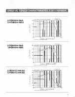
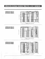
Page 19: ...uency r r r Full Step 4o Ex 100 SOO 115VAC 60HZ 2 8A PHASE W D 40 DAMPER a tep o H If S 4 EX 400 T 0 R Q 300 E 0 200 z l N 100 III1111 PULLOUT TORQUE J i r I I I r 0 01 0 1 t 10 100 SPEED x 1O TEPS SE...

Page 20: ...l SLEADS 23 6LENGTH ui siyie 3266 AWG22 SECTION AA r 335 en DRIVER UDX5128NA A i 0 1 tt t tr r2 NO 4 J tlfliC ij ij QJJ VEXTA 1 1 1 2 74 t lhlUIU LEAD DRIVER DRIVER WIRES TYPE MODEL NUMBER 5 5 NEW PEN...

Page 21: ...densing Free from dust or corrosive gas Free from water or oil Note When auach ng the driver In a close space such as control box o somewhere close to a hea1 rad atong object vent hole should be make...

Page 22: ...1 0 0 01 I l 0 1 1 10 100 SPEED x 1000 STEPS SEC fs rna imum no load starting heqvency 100 115VAC 60HZ 1 4A PHASE W 0 200AMPER Full Slep 4o Ex Half Step 4 50 Ex PULLOUT TORQUE 8 60 40 20 0 0 01 K 0 1...

Page 23: ...599H NBA PH599H NBA DOUBLE 5 5 NEW PENTAGON UOX5128NA UP05913H NAA PH5913H NAA SINGLE 5 5 NEW PENTAGON UDX5128NA UPD5913H NBA PH5913H NBA DOUBLE 5 5 NEW PENTAGON UDX5128NA o IMEN s o N s i _ t 1 0 I I...

Reviews: