Using the UPD motor driver package, the system
designer has total control over all of the important motion
profile parameters. As shown in Figure
2
,
each step pulse
received by the driver results in a motor movement of one
step. This makes control oL velocity, acceleration, de·
:::eleration and position simply a matter of controlling the
frequency (pulses per iecond) and number of pulses
sent to the driver.
A velocity of exactly one revolution per second can be
obtained from a 0.72 degree motor by sending pulses to
the driver at 500 pulses per second. Acceleration and
deceleration of the motor can be regulated by adjusting
the frequency of the pulses sent to the driver.
Position can also be readily controlled because the
amount or motor movement is equal to the number of
pulses applied to the driver, times the motor step angle.
For example, a 0.72 degree motor can be made to rotate
exactly one revolution by applying 500 pulses to the
driver.
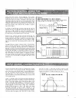
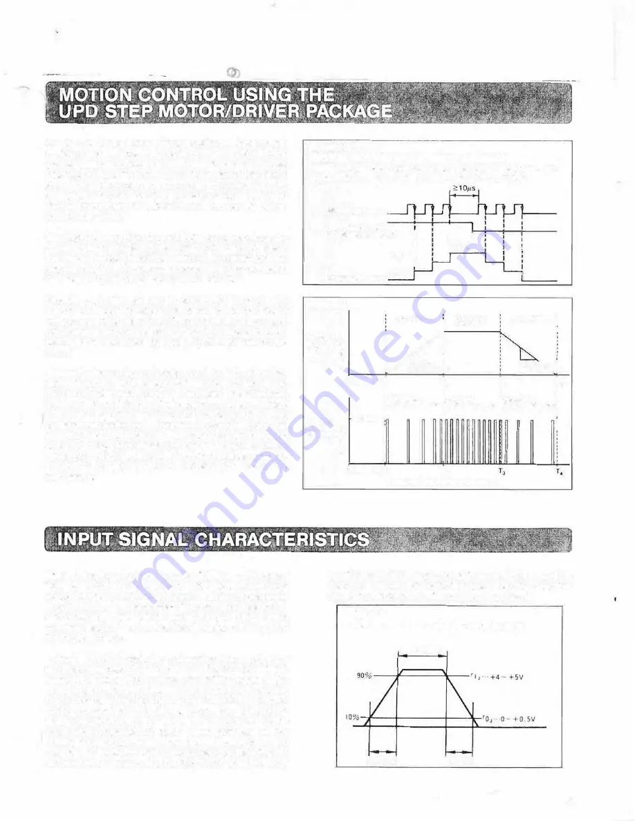
Figure 3shows a typical motion profile. In the time bet
ween T1 and T2, the lrequency
·
of the pulses being sent to
the driver increases, causing the motor to accelerate.
Between T2 and T3, the dnver receives pulses at a fixed
rate, and the motor turns at constant velocity. The pulses
to the driver decrease in frequency between T3 and T4,
until they stop. This causes the motor to slow down and
halt. The amount of shalt rotation in degrees is deter
mined by multiplying the total number of pulses between
T1 and T4 by the number of degrees per step of the
step motor
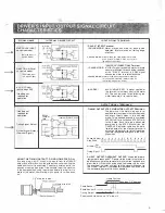
The input pulse waveform is shown in Figure 4.A logical
"ON" or"HIGH" is 4-5 volts, and "LOW" is be1ween 0-0.5
volts. The input pulse should have TIL timing characteris
tics: (i.e., the pulse rise and fafl times must be less than 1
microsecond). The noise liltering in the U PO driver
requires that the input pulses be stable for a minimum of
10 microseconds.
In the "1 PULSE" mode, the motor will rotate one step for
each pulse received at the driver's "PULSE" (STEP) ter
minal. The motor moves when the trailing edge of the
pulse is detected. (See Figure 2.) The direction of rota
tion is controlled by the signal at the "CW/CCW" (DI REC
TION) terminal of the driver When the "CW/CCW"
(DIRECTION) terminal is "HIGH", the motor will rotate
one step clockwise for each pulse received at the
"PULSE" (STEP) terminal. The motor will rotate one step
counter-clockwise for each pulse received at the "PULSE"
terminal when the signal at the "CW/CCW" (DIRECTION)
Figure 2
MOTOR MOVEMENT VS. INPUT SIGNALS
NOTE:
The direction input signal should be changed only while the
step pulse signal is not being sent and is "LOW" or "OFF".
Step Pulse Input
Input for Direction
I
ot Rotation CW/CCW
:
I
I
�10:
I
I
CW
I
_LI
1- 11s,
Motor Movement CCW
Figure 3
MOTOR
l
VELOCITYl;:
PROFILE 0
0
.,
"'
>
ACCEL(RATE
CONSTANT
I
VElOCl'I'(
IALI.
OECElERATE
!
'
St.OPE•,
:
DECELERATION
0 TIME+-�'
:,
;3
;•
I
:
:
:
l1NCREASING
'CONSTANT
'DECREASING
'
l
I PULSE FREOUENCY;PULSE FREOUENCV:PULSE. fR(OUENC'f:
!
I
•
I
+4-SV
'
'
'
PULSE
f
:
TIMING
w
.
I
I
DIAGRAM�
:
:
....
.
:
�
!
l
:
j
OTIME-T,
T,
TYPICAL MOTION PROFILE
terminal is "LOW', or the signal 1s absent. Care must be
taken so lhe step signal 1s inactive when the direction
signal is changed. or missed steps may result.
Figure 4
INPUT PULSE CHARACTERISTICS
5
µ
s MIN
2
µ
s MAX
2,.s MAX
4

