-
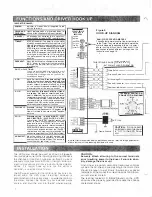
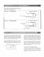
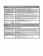
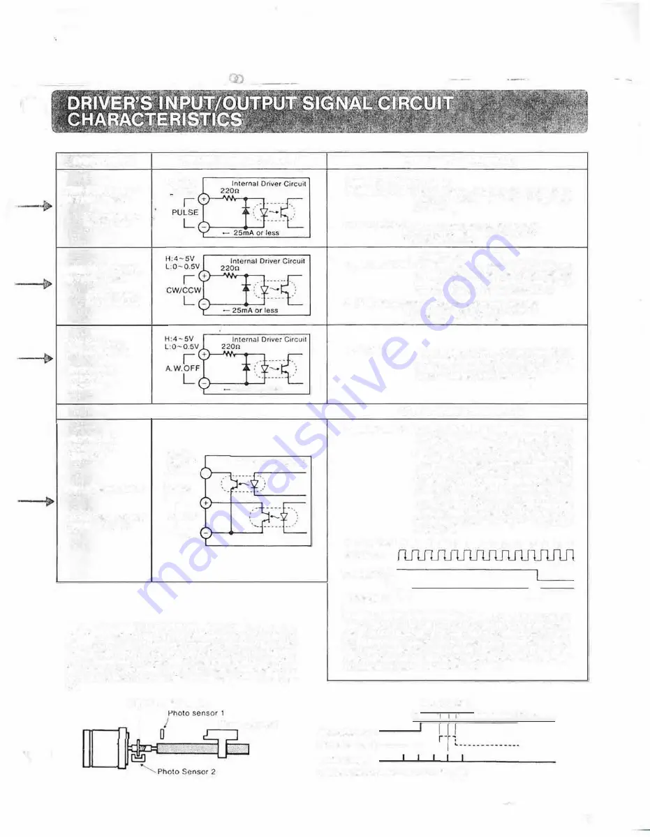
SIGNAL NAME
STEP PULSE INPUT
(in
1
pulse mode)
(CW step ,npvt 1n
2
putsc mode)
DIRECTION SIGNAL
(in 1 pulse mode)
(CCW step onput
in 2 pulse model
A. W. OFF input
(All Windings Off)
·Hook-up not
required for
operation
•Hook-up not
required for
operation
Timing Signal Output
O.Heat Signal Outpul
(Overheat Signal)
.,
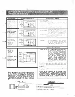
INTERNAL DRIVER CIRCUIT
H:4-SV
l:0-0.SV
OC24V
10mA or
less
r-
+
�
COM
25mA or less
Internal Driver Circuit
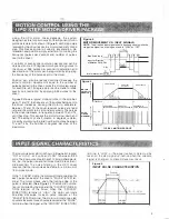
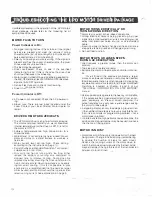
USING THE TIMING OUTPUT TO FIND HOME POSITION:
By usong a logic ·AND"' circuit. with inputs lrom the TIMING
oulput. and a HOME swllch, lhe exlernal con I roller can find the
home position to tl'le exacl step. The dnver powers·up with the
phases in the step e> position. II 1s desirable to put the machine
in the home position using lhis method before turning ,1 otl. to
prevent the molor from moving when power 1s turned back
on.
7.2
°
wide slit in disk·
I
-Home direction
INPUT SIGNAL TERMINALS:
"PULSE" (STEP) Terminal
1 PULSE MOOE: Motor moves one step for each pulse
detected. (Motor moves on trailing edge
of pulse.)
2 PULSE MOOE: Motor moves one step clockw,se for eacn
Pulse detected (Motor moves on 1ne 1,a,I·
1n9 edge of the pulse I
"CW/CCW'' (DIRECTION) Terminal
1 PULSE MODE: A "HIGH" signal causes the motor to rotate
counter-clockwise for each pulse received
at tile "PULSE" terminal. A "LOW' signal
causes the motor to rotate clockwise.
2 PULSE MOOE: Motor moves one step counicr•clockwlse
for eacn puls� detected (Motor moves on
the tra,long edge of the pulse)
A.W. OFF:
ALL WINDINGS OFF. A signal applied at
this term1nat turns the current to the motor
off. This can be used for positioning the
motor manually. or to reduce heat.
OUTPUT SIGNAL TERMINALS:
TIMING OUTPUT STEP flJ MONITOR OUTPUT TERMINAL:
The polarity of lhe motor windings is re·
pealed every ten steps in the lull step mode,
and every twenty steps in the half step
mode. This phase sequence is numbered
STEP 0 to 9 for full step and STEP f2J to 19
tor
half step. Each time the phases are
energized In the STEP 0 condition. the
TIMING LED indicator lights and the opto·
isolated output of lhe monitor lerminal 1s
activated. When the driver is first !urned on,
the motor phases are energized in the STEP
fi?J posi!ion.
Phase Number l!1 1 2 3 4 5 6 7 e
g
g 9 e 7
Step Pulse
Direction CW
ccw
Timing Signal
LJ
'
LJ
O.HEAT OUTPUT-OVERHEAT OUTPUT: When the driver's
temperature reaches 80
<
C, power to the motor is removed. In
applications where the removal of motor current poses a pro
blem. the A.H.O. switch can be used to disable lhis function.
The overheat indicator will light and lhe signal will be sent to
the O.HEAT terminal if the temperature exceeds so• even with
the automatic power off function disabled.
Photo Sensor 1
Home Position
ON
Less lhan 7.2"degrees
·Photo Sensor 2 -------'
Timong Output
·The disk should have one 7.2
°
wide sill
8

