3
How to install the motor
●
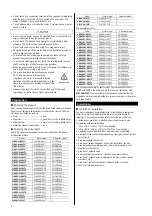
Round shaft type
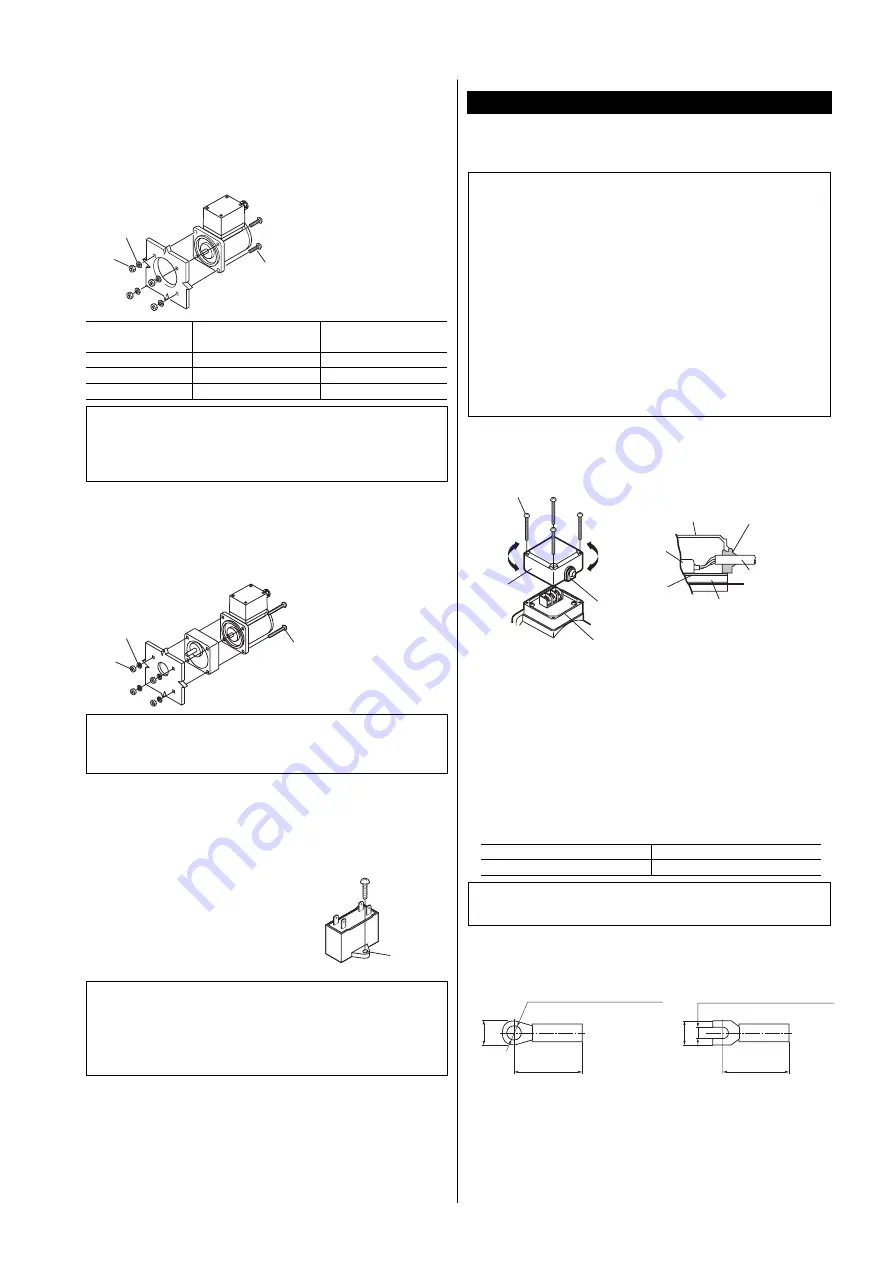
Drill holes on the mounting plate and fix the motor on the plate using
screws, nuts, and washers (not supplied). Be careful there is no gap
between the motor installation surface and the bracket.
Motor
Mounting screws
Mounting plate
Nuts
Washers
First number of
motor model
Nominal diameter of
screw
Tightening torque
2
M4
2.0 N·m (17.7 lb-in)
4
M5
2.5 N·m (22 lb-in)
5
M6
3.0 N·m (26 lb-in)
Note
Do not insert the motor into the mounting hole at an angle or
force it in, as this may scratch the flange pilot section and
damage the motor.
●
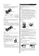
Pinion shaft type
Drill holes on the mounting plate and fix the motor and gearhead on the
plate using screws supplied with the gearhead. Be careful there is no gap
between the motor flange and the gearhead. For details of installation, see
the operating manual provided with the gearhead, which is sold separately.
Motor
Gearhead
Screws provided
with gearhead
Mounting plate
Nuts
Washers
Note
Use the gearhead with pinion shaft which is identical with one of
motor.
●
Motor with cooling fan
When installing a motor with cooling fan onto a device, leave 10 mm
(0.39 in.) or more behind the fan cover or open a ventilation hole so that
the cooling inlet on the back of the motor cover is not blocked.
Mounting the capacitor (Only for single-phase motors)
Before mounting the provided capacitor,
check that the capacitor’s capacitance matches
that stated on the motor’s name plate. Mount
the capacitor securely by using M4 screws
(not provided).
Ø4.3 mm
(Ø0.169 in.)
Note
Do not let the screw fastening torque exceed 1 N·m (8.8 lb-in)
to prevent damage to the mounting foot.
Mount capacitor at least 10 cm (3.94 in.) away from the motor.
If it is located closer, the life of the capacitor will be shortened.
Connection and operation
Insulate all the wire connections, such as the connection between the
motor and the capacitor connection. Use the supplied capacitor cap to
insulate the capacitor terminal connection.
Note
Insulation class of this motor is B.
Make sure that the motor case temperature does not exceed
90 °C (194 °F) during operation of the motor. Operation
exceeding case temperature 90 °C (194 °F) may significantly
deteriorate the coils and ball bearings of the motor and shorten
the motor’s life span. Motor case temperature can be
measured by fixing a thermometer on the motor surface. It can
also be measured using thermo tape or a thermocouple.
To change rotation direction of the single-phase induction
motor, wait until the motor completely stops. Otherwise its
direction may not change or may take much time to change.
Single-phase motors use a capacitor and keep it connected
even after rotation of the motor has started.
Connection method to a terminal box
●
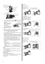
6 W types
Rubber bush
Terminal
cover screws
Rubber seat
Rubber seat
Terminal
box cover
Rubber bush
Cable
Terminal plinth
Terminal box cover
Terminal
block
•
For wiring, be sure to use cable that meets the following specifications.
Cable: Diameter is Ø6.8 to 8.6 mm (Ø0.27 to 0.33 in.)
•
When sealing the terminal cover, ensure that no scraps or particles get
caught between the contact surfaces.
•
In order to maintain a tight seal around the terminal box, the rubber seat
use between terminal box cover and terminal plinth. Also this terminal
box is constructed to hold a rubber seat. If this rubber comes out of the
box, please seat it correctly on the box.
•
Also refer to the tightening torque table to determine the appropriate
tightening torque to use when fastening the terminal box cover and
terminal block.
Terminal box cover
0.3 N·m (42 oz-in.)
Motor connecting terminals
0.8 to 1.0 N·m (113 to 142 oz-in.)
Note
Use a cable of an appropriate diameter.
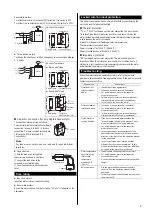
Appropriate terminal strip
Ring terminal with insulation
Fork terminal with insulation
Ø3.6 mm (Ø0.14 in.) or more
Ø3.6 mm (Ø0.14 in.) or more
18 mm (0.71 in.) or less
7.2 mm (0.283 in.) or less
18 mm (0.71 in.) or less
6.4 mm (0.25in.) or less
•
Cable entry is possible at any of the four sides of the terminal box.
Undo the screws which fixed terminal box to the motor case, position
the terminal box so that the outlet faces in the desired direction and re
fasten the screws.


