


Connection
▌
14
7
Connection
This chapter explains how to connect the motor, power supply and I/O signals to the driver, as well as grounding
method.
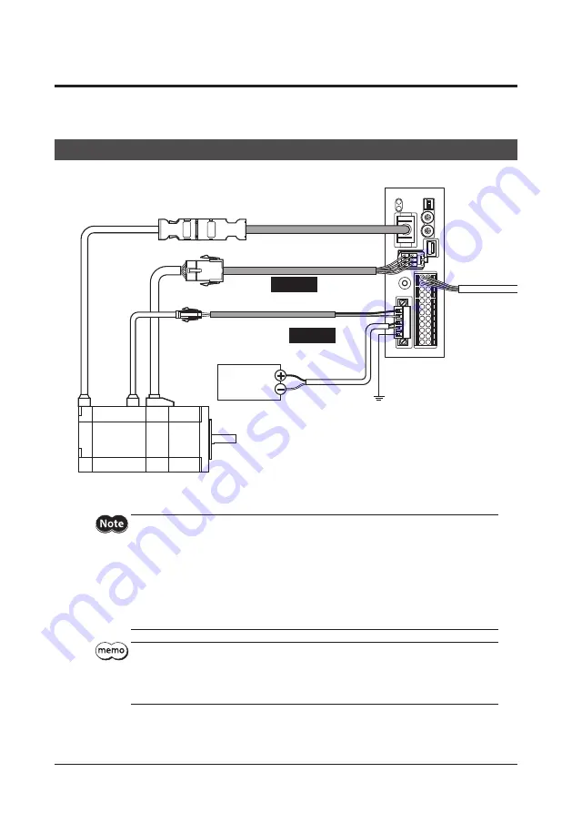
7-1 Connection
method
The following fi gure shows models for the electromagnetic brake type.
Connect to CN2
Connect to CN4
I/O signals
Connect to CN3
Black
White
Connect to CN1
DC power supply
24 VDC±5% or
48 VDC±5%
Grounding
Connect to MB1 and MB2
Cable for encoder
Cable for motor
Cable for electromagnetic brake
Required
Required
+24 V (+48 V)
GND
* Cables represented in gray color are accessories. Use the cable for encoder when the length of the encoder cable of
motor is not enough.
Have the connector plugged in securely. Insecure connections may cause malfunction or damage
to the motor or driver.
Do not wire the power supply cable of the driver in the same cable duct with other power lines or
motor cables. Doing so may cause malfunction due to noise.
The lead wires of the "cable for electromagnetic brake" have polarities, so connect them in the
correct polarities. If the lead wires are connected with their polarities reversed, the electromagnetic
brake will not operate properly.
Keep 20 m (65.6 ft.) or less for the wiring distance between the motor and driver. To extend more
than 20 m (65.6 ft.) may result in the driver heat generation or increase of the electrical noise
emitted from the product.
When plugging/unplugging the connector, turn off the power and wait for the POWER/ALARM
LED to turn off before doing so.
When unplugging the motor cable, do so while pressing the latches on the connector.
When installing the motor on a moving part, use an accessory fl exible cable having excellent fl ex
resistance.


