


Setting
▌
28
9 Setting
This chapter explains how to set the motor and driver functions.
9-1
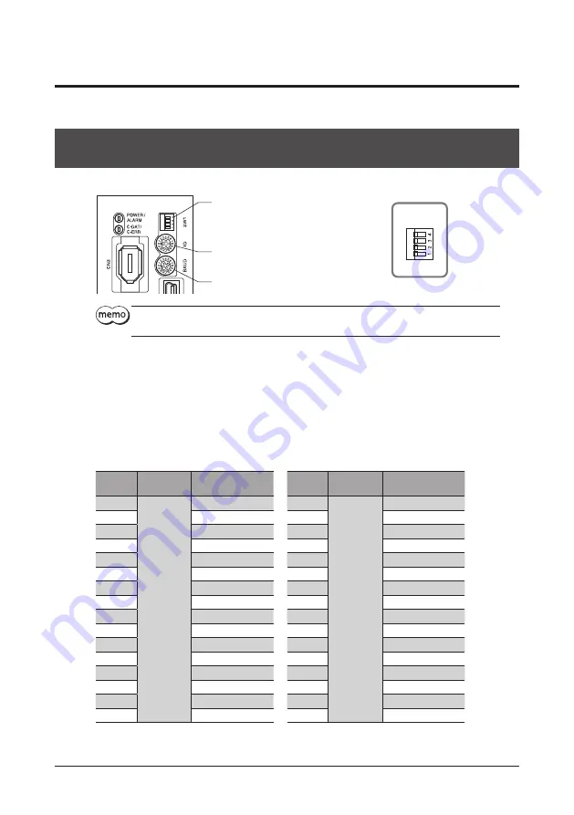
Setting of the built-in controller type and pulse input type with RS-
485 communication interface
The fi gure shows the built-in controller type driver.
Address number setting switch (ID)
Transmission rate setting switch (BAUD)
Function setting switch (SW1)
No.3, No.4: Sets the Termination resistor.
No.2: Sets the protocol.
No.1: Sets the address number (slave address).
→
ON
SW1
Be sure to turn off the driver power before setting the function setting switch (SW1). The new setting
of the SW1 will become eff ective after the power is cycled.
About resolution
The initial value of resolution of the driver is 1000 P/R. The initial value of resolution may vary depending on the
product connected. Check with the operating manual of the motor or motorized actuator used.
Address number (slave address)
Set the address number (slave address) using the address number setting switch (ID) and SW1-No.1 of the function
setting switch. Make sure each address number (slave address) you set for each driver is unique.
Factory setting
Built-in controller type; ID: 0, SW1-No.1: OFF
Pulse input type with RS-485 communication interface; ID: 1, SW1-No.1: OFF
ID
SW1-No.1
Address number
(slave address)
ID
SW1-No.1
Address number
(slave address)
0
OFF
0 *
0
ON
16
1
1
1
17
2
2
2
18
3
3
3
19
4
4
4
20
5
5
5
21
6
6
6
22
7
7
7
23
8
8
8
24
9
9
9
25
A
10
A
26
B
11
B
27
C
12
C
28
D
13
D
29
E
14
E
30
F
15
F
31
* In the case of Modbus protocol, the address number (slave address) 0 is reserved for broadcasting, so do not use this
address.


