Installation
−11−
4.3 Installing the driver
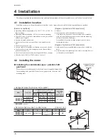
The driver is designed so that heat is dissipated via air convection and conduction through the enclosure.
There must be a clearance of at least 25 mm (0.98 in.) and 50 mm (1.97 in.) clearances in the horizontal and vertical directions,
respectively, between the driver and enclosure or other equipment within the enclosure.
Installation direction
Install the driver so that the front panel side
of the driver is turned in the front direction or
upward.
If the 400 W type driver is installed with the
front panel side facing upward, the operating
ambient temperature is 0 to +35°C (+32 to
+95°F).
Mounting
plate
Front direction
Operating ambient temperature:
0 to +40 °C (+32 to +104 °F)
Operating ambient temperature
200 W type: 0 to +40 °C
(+32 to +104 °F)
400 W type: 0 to +35 °C
(+32 to +95 °F)
Mounting
plate
Mounting
plate
Upward direction
Note
•
Do not install any equipment that generates a large amount of heat or noise near the driver.
•
If the ambient temperature of the driver exceeds the upper limit of the operating ambient temperature,
revise the ventilation condition or force-cool the area around the driver using a fan.
Installation method
Install the driver to a flat metal plate offering excellent vibration resistance.
Remove the front panel of the driver and secure the two mounting holes using screws and nuts (M4: not supplied).
Tighten the screws until no gaps remain between the driver and mounting plate.
Screw (M4: not supplied)
Tightening torque: 0.5 to 0.7 N·m (4.4 to 6.1 lb-in)
•
Plate cutout for mounting
Nut
Washer
2×Ø4.5 (Ø0.177)
15±
0.2
(0.59±
0.008
)
[Unit: mm (in.)]
1
15±
0.2
(4.53±
0.008
)
106
+
1
0
(4.17
+
0.04
0
)
62
+ 1
0
(2.44
+ 0.04
0
)
15±
0.2
(0.59±
0.008
)
Note
•
The space between the mounting hole section and front panel of the driver is 6 mm (0.24 in.).
Therefore, the total height of the screw head and washer should be less than 6 mm (0.24 in.).
The front panel cannot be installed if it is exceeded 6 mm (0.24 in.).
•
If the washer is used, use the washer which outer diameter is 10 mm (0.39 in.) or less.
Removing and installing the front panel
Removing
Remove the front panel
having the under side.
Installing
Install the front panel after
placing on the upper side of
the driver front face.
Summary of Contents for BMU5200A Series
Page 43: ...43...


