Convenient functions
−27−
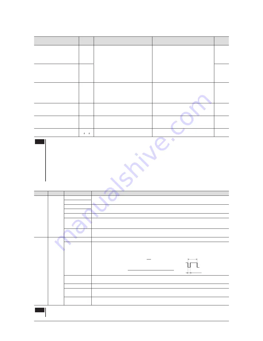
Item
Display
Description
Setting range
Factory
setting
OUT0 output function
selection
oUt0
Assigns the output signals to the
external output terminals.
----
Not used
AL-1
ALARM-OUT1
Sp
SPEED-OUT
AL-2
ALARM-OUT2
~
nouE
MOVE
uA
VA
_
wnG
WNG
Sp
OUT1 output function
selection
oUt1
AL-1
Overload alarm detection
time except when holding a
shaft
oLt~
n
Sets the time to output the alarm
after detecting the overload condition
when a load up to the limited duty
region exceeding the continuous duty
region was applied.
0.1 to 60.0 s
30.0
Overload warning level
oL-L
Sets the detection level (load factor) for
the overload warning function based
on the rated current being 100%.
50 to 120%
120
Rotation speed attainment
band
uA
Sets the band within which the
rotation speed of the motor is deemed
to have reached the set value.
0 to 400 r/min
200
Initialize the parameter
mode
n
Restores the value set in the
parameter mode to the factory setting.
−
−
Note
•
Do not turn off the motor power while the initialization is still in progress (= while the display is blinking).
Doing so may damage the data.
•
When setting the speed increasing ratio to 1.00, the speed reduction ratio will be effective. When setting the
speed increasing ratio to other than 1.00, the speed increasing ratio will be effective.
•
When setting a longer time in the "overload alarm detection time except when holding a shaft" parameter,
an overload status may continue. Repeating this condition may result in shorter service life of the motor and
gearhead.
•
If a load exceeding the limited duty region was applied, the "overload alarm detection time except when holding
a shaft" is maximum 5 seconds.
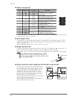
Description of I/O signals
Signal Terminal
Signal name
Description
Input
IN0
IN1
IN2
IN3
IN4
FWD
The motor rotates when either of the FWD input or REV input is turned ON. If the FWD
input and REV input are turned ON simultaneously, the motor stops instantaneously.
REV
M0
These signals are used to select the operation data number. If both signals are turned
OFF, the operation data No.0 is selected.
M1
ALARM-RESET This signal is used to reset the alarm. Refer to p.34 for timing chart.
EXT-ERROR
When turning this signal OFF, an alarm generates and the motor stops instantaneously.
Then "
AL6E
" will be shown on the display (normally closed).
H-FREE
The slight position-keeping is released when the H-FREE input is turned ON.
(When the slight position-keeping selection is set to "Enable")
Output
OUT0
OUT1
ALARM-OUT1 This signal is output when an alarm generates (normally closed).
SPEED-OUT
30 pulses are output with each revolution of the motor output shaft synchronously with
the motor operation. The pulse width of output pulse signals is 0.2 ms. You can use the
SPEED-OUT output to calculate the motor speed.
Rotation speed (r/min) =
× 60
SPEED-OUT output frequency
30
SPEED-OUT output frequency (Hz) =
1
T
T
0.2 ms
ALARM-OUT2 This signal is output when exceeding the overload warning level.
Or this signal is output when an overload alarm generates (normally closed).
MOVE
This signal is output while the motor is operating.
VA
This signal is output when the motor rotation speed becomes equal the value set by the
rotation speed attainment band parameter.
WNG
This signal is output when a warning generates. (The motor will continue to operate.)
When the warning is released, it will automatically turn OFF.
Note
Do not assign the same input signal to multiple input terminals. When the same input signal is assigned to
multiple input terminals, the function will be executed if any of the terminals becomes active.
Summary of Contents for BMU5200A Series
Page 43: ...43...


