Preparation
−7−
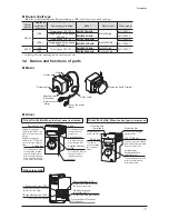
Round shaft type
in the model name indicates
A
(no machining) or
AC
(shaft flat) for the round shaft type.
Output
power
Degree of
protection of
the motor
Power supply voltage
Model
Motor model
Driver model
200 W
IP40
Single-phase 100-120 V
BMU5200A-
BLM5200-
BMUD200-A
Single-phase/Three-phase
200-240 V
BMU5200C-
BMUD200-C
IP65
*
Single-phase 100-120 V
BMU5200AP-
BLM5200P-
BMUD200-A
Single-phase/Three-phase
200-240 V
BMU5200CP-
BMUD200-C
400 W
IP40
Three-phase 200-240 V
BMU5400S-
BLM5400-
BMUD400-S
IP65
*
BMU5400SP-
BLM5400P-
*
Excluding the motor mounting surface and connector part.
3.4 Names and functions of parts
Motor
Output shaft
Motor
Gearhead
Protective Earth Terminal
Motor cable
Motor connector
(White)
Sensor connector
(Black)
Mounting hole
(4 locations)
Driver
Driver front side:
When the front panel is attached
Driver front side:
When the front panel is removed
Display
Front panel
This display shows
the monitor item,
alarms, etc.
Setting the operation
switch to the "RUN" side
causes the motor to start
running.
Setting the operation
switch to the "STAND-BY"
side causes the motor to
stop.
This switch is used to
change the motor
rotation direction.
This setting dial is used
to change the rotation
speed or parameters.
After changing, the new
value is determined by
pressing the setting dial.
Rotation direction
switch
Operation switch
Setting dial
Use after removing
the protective film.
Protective film
This key is used to change
the display of the operation
mode or the function.
FUNCTION key
Installs the driver
with screws (M4).
Mounting hole
(2 locations)
This key is
used to change
the operation
mode.
MODE key
This potentiometer is used
to set the acceleration/
deceleration time.
Acceleration/
deceleration time
potentiometer
Use after removing the
protective film.
Protective film
Driver rear side
Protective Earth Terminal
(2 locations)
Main power supply
connector (CN1)
Connects the main power supply.
Motor connector (CN2)
Connects the motor connector
(white) from the motor.
Sensor connector (CN3)
Connects the sensor connector
(black) from the motor.
I/O signals connector (CN4)
Connects the I/O signals.
Summary of Contents for BMU5200A Series
Page 43: ...43...


