Installation
−8−
4 Installation
This chapter explains the installation location and installation methods of the motor and driver, as well as how to install a load.
4.1 Installation location
Install the motor in a well-ventilated place where they can be inspected easily and the following conditions are satisfied:
[Common conditions]
•
Operating ambient temperature: 0 to +40 °C (+32 to +104 °F)
(non-freezing)
•
Operating ambient humidity: 85% or less (non-condensing)
•
Area that is free of explosive atmosphere or toxic gas (such as
sulfuric gas) or liquid
•
Area not exposed to direct sun
•
Area free of excessive amount of dust, iron particles or the
like
•
Area free of excessive salt
•
Area not subject to continuous vibration or excessive shocks
•
Area free of excessive electromagnetic noise (from welders,
power machinery, etc.)
•
Area free of radioactive materials, magnetic fields or vacuum
•
Altitude: Up to 1000 m (3300 ft.) above sea level
[Degree of protection: IP65 rated motor]
•
Indoors
•
Not exposed to oil (oil droplets) or chemicals.
This motor can be used in an environment that is splashed
with water (excluding the connector part and the mounting
surface of the round shaft type).
Not available for use under high pressure jets of water or
immersion in water.
[Degree of protection: IP40 rated motor]
•
Inside an enclosure installed indoors (provide a ventilation
hole)
•
Area not subject to splashing water (rain, water droplets), oil
(oil droplets) or other liquids
4.2 Installing the motor
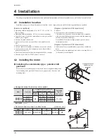
Installing the combination type
•
parallel shaft
gearhead
Secure the motor with hexagonal socket head screws (supplied) through the
four mounting holes provided. Do not leave a gap between the motor and
mounting plate.
Hexagonal socket
head screw set
(supplied)
•
Hexagonal socket head screw set (supplied)
Motor
Gearhead
L2
L1
Model
Gear ratio
Hexagonal socket head screw
(Material: Stainless steel)
Tightening
torque
[N·m (lb-in)]
Screw
size
L1
[mm (in.)]
L2
[mm (in.)]
BMU6200
BMU6400
5 to 20
M8
85 (3.35)
11 (0.43)
12 (106)
30, 50
100 (3.94)
14 (0.55)
100
*
, 200
*
110 (4.33)
10 (0.39)
*
BMU6200
type only
•
Recommended mounting hole dimensions
[Unit: mm (in.)]
Model
ØA
B
ØC
D
E
D
B
B
ØC
ØA
4×E
BMU6200
BMU6400
120 (4.72)
84.86 (3.341)
41
+ 0.025
0
(1.6142
+ 0.0010
0
) 20 (0.79)
M8
Summary of Contents for BMU5200A Series
Page 43: ...43...


