background image

Installation

−9−


„

Removing/Installing the gearhead

See the following steps to replace the gearhead or to change the cable position.

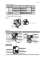
1.  Removing the gearhead

Remove the hexagonal socket head screws assembling the 

motor and gearhead and detach the motor from the gearhead.

Hexagonal socket head screw


Assembly hexagonal socket head screw

Model

Screw size

Tightening torque

BMU6200 

BMU6400

M3

0.6 N·m (5.3 lb-in)

2.  Installing the gearhead

Using the pilot sections of the motor and gearhead as guides, 

install the gearhead to the motor and tighten the hexagonal 

socket head screws.

Confirm that no gaps remain between the motor flange 

surface and the end face of the gearhead pilot section.

At this time, the motor cable position can be changed to a 

desired 90° direction.

When installing the gearhead, slowly rotate it clockwise/

counterclockwise to prevent the pinion of the motor output 

shaft from contacting the side panel or gear of the gearhead.

Install using pilot
sections as guides

Change the cable
position to a desired
90° direction.

Note


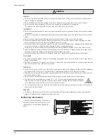
Do not forcibly assemble the motor and gearhead. Also, do not let metal objects or other foreign 

matter enter the gearhead. The pinion of the motor output shaft or gear may be damaged, 

resulting in noise or shorter service life.


Do not allow dust to attach to the pilot sections of the motor and gearhead. Also, assemble the 

motor and gearhead carefully by not pinching the O-ring at the motor pilot section. If the O-ring is 

crushed or severed, grease may leak from the gearhead.


The hexagonal socket head screws assembling the motor and gearhead are used to attach the 

motor and gearhead temporarily. When installing the motor/gearhead assembly, be sure to use 

the supplied hexagonal socket head screws.


„

Installing the round shaft type

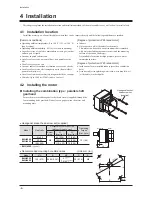
Secure the motor with hexagonal socket head screws (not supplied) through 

the four mounting holes provided.

Do not leave a gap between the motor and mounting plate.

Install the motor to a mounting plate of the following size or larger, so that 

the motor case temperature will not exceed 90 °C (194 °F).

Hexagonal socket head screw

(not supplied)

Model

Size of mounting plate

[mm (in.)]

Thickness

[mm (in.)]

Material

BMU5200

200×200 (7.87×7.87)

5 (0.20)

Aluminum alloy

BMU5400

250×250 (9.84×9.84)

6 (0.24)


Applicable mounting screw

Model

Screw size

Tightening torque

BMU5200 

BMU5400

M8

15.5 N·m (137 lb-in)

[12 N·m (106 lb-in) ]

*

The brackets [  ] indicate the value for stainless steel.


Recommended mounting hole dimensions 

[Unit: mm (in.)]

Model

ØA

B

ØC 

*

D

ØC

B

B

ØA

4×D

BMU5200 

BMU5400

104 (4.09)

73.54 (2.895)

83 

+ 0.035 
  0

(3.2677

+ 0.0014 
  0

)

M8 or

Ø8.5 (0.335)

ØC indicates the pilot diameter on the flange.


Note

Do not install the motor to the mounting hole diagonally or assemble the motor forcibly.

Doing so may cause damage to the flange pilot section, thereby resulting in damage to the motor.

Summary of Contents for BMU5200A Series

Page 1: ...400 W OPERATING MANUAL Thank you for purchasing an Oriental Motor product This Operating Manual describes product handling procedures and safety precautions Please read it thoroughly to ensure safe op...

Page 2: ...2 8 Convenient functions 23 8 1 Functions list 23 8 2 Setting items and panel displays 24 8 3 Parameter list 26 8 4 Items displayed on the driver 28 8 5 Setting the operation data 29 8 6 Setting the a...

Page 3: ...ng the operation without removing the cause of the problem may result in malfunction of the motor and driver leading to injury or damage to equipment Installation The motor and driver are Class I equi...

Page 4: ...ay result Securely install the load on the motor gearhead output shaft Inappropriate installation may result in injury Connection Be sure to ground the product to prevent it from being damaged by stat...

Page 5: ...on when using under low temperature environment When an ambient temperature is low since the load torque may increase by the oil seal or viscosity increment of grease used in the gearhead the output t...

Page 6: ...flat Degree of protection of the motor P IP65 blank IP40 Power supply input A Single phase 100 120 V C Single phase Three phase 200 240 V S Three phase 200 240 V Output power 200 200 W 400 400 W Moto...

Page 7: ...he operation switch to the RUN side causes the motor to start running Setting the operation switch to the STAND BY side causes the motor to stop This switch is used to change the motor rotation direct...

Page 8: ...plets or chemicals This motor can be used in an environment that is splashed with water excluding the connector part and the mounting surface of the round shaft type Not available for use under high p...

Page 9: ...sections of the motor and gearhead Also assemble the motor and gearhead carefully by not pinching the O ring at the motor pilot section If the O ring is crushed or severed grease may leak from the ge...

Page 10: ...on parts Gearhead model Screw size Effective depth GFV6G M6 12 mm 0 47 in Permissible radial load and permissible axial load The radial load and the axial load on the output shaft of the motor gearhea...

Page 11: ...r exceeds the upper limit of the operating ambient temperature revise the ventilation condition or force cool the area around the driver using a fan Installation method Install the driver to a flat me...

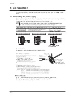
Page 12: ...ted L1 L2 and L3 only Connector model FKC2 5 3 ST 5 08 LR PHOENIX CONTACT GmbH Co KG Connecting the lead wire Connect to insert the lead wire to the connector Applicable lead wire AWG18 to 14 0 75 to...

Page 13: ...nit mm in Driver Two Protective Earth Terminals PE are provided on the driver Ground either of the two Protective Earth Terminals near the driver You can ground either of the two Protective Earth Term...

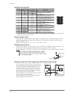
Page 14: ...er supply 24 VDC 15 to 20 100 mA or more Output signal circuit The driver outputs signals are photocoupler open collector output The ON voltage of the output circuit is max 1 5 V When driving each ele...

Page 15: ...round Motor connection Motor ground NC Motor connector CN1 CN2 N L PE Motor Main circuit Control circuit Driver CN4 4 7 IN COM1 0 V 5 0 V N Circuit breaker Shielded cable Functional grounding 820 IN1...

Page 16: ...e case of 5 VDC 150 to 560 0 5 W Source logic 24 VDC CN4 4 5 to 30 VDC 100 mA or less 100 mA or less 0 V 5 6 4 3 2 1 6 6 k 6 6 k 6 6 k 6 6 k 6 6 k 820 820 820 820 820 12 R R 10 11 9 Programmable contr...

Page 17: ...the input voltage 200 W type 400 W type Note When cycling the power or plugging unplugging the connector turn off the power and wait for 1 minute or more before doing so Ensure that the connector plug...

Page 18: ...et data is saved in the operation data No 0 Refer to p 24 for details Confirmation If the setting dial is pressed while the motor stops the set speed is displayed blinking several times Operating with...

Page 19: ...d relays Operation This operation example is for when the rotation speed is set to the operation data No 0 Setting the External operation signal input parameter The external operation signal input par...

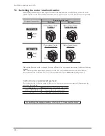
Page 20: ...ayed The data mode parameter mode and the I O monitor of the monitor mode are enabled possible to set The display time of rE varies depending on the switch When setting the operation switch to the RUN...

Page 21: ...the motor by selecting any of the operation data No 0 to No 3 based on a combination of ON OFF status of the M0 and M1 inputs The motor is operated using the rotation speed acceleration time and dece...

Page 22: ...ise CCW CW If the rotation direction switch is changed the motor will decelerate to a stop and start rotating in the direction being switched If the external operation signal input parameter is set to...

Page 23: ...nal is output Setting Rotation speed Sets the motor rotation speed using the setting dial 18 Sets the motor rotation speed in the operation data 29 Acceleration time deceleration time Sets using the a...

Page 24: ...ed Return to the input monitor Input monitor Output monitor Data mode Return to the rotation speed 0 Return to the operation data No 0 Operation data No 0 Rotation speed 0 Acceleration time 0 Decelera...

Page 25: ...ing Data setting Data setting Data setting Speed upper limit Data setting Speed lower limit Data setting Data setting Data setting Signal selection 0 Signal selection 0 Data setting Signal selection 4...

Page 26: ...ArSt Resets using the ALARMRESET input or the alarm reset on the monitor mode Analog acceleration deceleration time tAtD Changes the setting method of acceleration deceleration time An Sets using the...

Page 27: ...I O signals Signal Terminal Signal name Description Input IN0 IN1 IN2 IN3 IN4 FWD The motor rotates when either of the FWD input or REV input is turned ON If the FWD input and REV input are turned ON...

Page 28: ...eration data No currently selected Alarm AL00 When an alarm generates the alarm code is displayed You can also reset alarms or check and clear alarm records Refer to p 33 for alarm type Warning _ wn00...

Page 29: ...d as follows 20 4 1300 63 7 Conveyor transfer speed m min Accordingly 20 4 is shown on the panel Display while an alarm generates The alarm code is displayed while the alarm generates and the screen c...

Page 30: ...min from the standstill state Deceleration time The deceleration time is set as the time needed for the motor to stop from the rated rotation speed 3000 r min Acceleration time Deceleration time r min...

Page 31: ...is setting range can be changed to limit Setting range of the rotation speed r min r min Example When limiting the speed range by setting to the speed upper limit to 3000 r min and the speed lower lim...

Page 32: ...ameter Up to 50 of the rated torque is generated according to the angle variation of the motor output shaft figure The position of a load exceeding 50 of the rated torque cannot be kept When the power...

Page 33: ...driver and motor AL30 Overload A load exceeding the continuous duty region was applied to the motor for the time exceeded the value set in the overload alarm detection time except when holding a shaf...

Page 34: ...the operation signal is the FWD input ALARM OUT1 output ON OFF ALARM RESET input ON OFF FWD input Motor operation ON OFF 10 ms or more 10 ms or more CW CW Stop Reset with the monitor mode Set the oper...

Page 35: ...w the ambient temperature Review the ventilation condition in the enclosure _ wn30 Overload A load exceeding the overload warning level parameter was applied to the motor Check the load condition _ wn...

Page 36: ...eed The motor rotates in the direction opposite to the specified direction The FWD input and REV input are connected wrongly or otherwise not connected correctly Check the connection of the FWD input...

Page 37: ...uct The driver uses semiconductor elements so be extremely careful when handling them Electrostatic discharge can damage the driver During inspection Are any of the motor gearhead mounting screws loos...

Page 38: ...ignments of the motor cable that comes out of the motor The following figure is as view from the direction of the motor lead wires side Motor connector White Pin No Color Lead eire 6 5 4 3 2 1 Housing...

Page 39: ...the signal cables CN4 by means of double insulation Applicable Standards Motor EN 60034 1 EN 60034 5 EN 60664 1 Driver EN 61800 5 1 Installation conditions EN Standard Motor Driver For incorporating...

Page 40: ...provides in the power line in order to prevent the noise generated within the driver from propagating outside via the AC input line For mains filters use the products as shown in the chart or an equiv...

Page 41: ...y providing a minimum clearance of 100 mm 3 94 in between them If they must cross do so at a right angle Place the AC input cable and output cable of a mains filter separately from each other Use a co...

Page 42: ...freezing Ambient Humidity 85 or less non condensing Altitude Up to 1000 m 3300 ft above sea level Surrounding atmosphere No corrosive gas or dust Cannot be used in radioactive materials magnetic fiel...

Page 43: ...43...
Page 44: ...nowledged The third party products mentioned in this manual are recommended products and references to their names shall not be construed as any form of performance guarantee Oriental Motor is not lia...

Reviews: