


HM-40089-3
5-phase stepping motor unit
CRK
Series
Built-in Controller
Information
Thank you for purchasing an Oriental Motor product.
1
Introduction
Before use
Only qualified personnel should work with the product. Use the product correctly
after thoroughly reading the section “Safety precautions”.
The product described in this manual has been designed and manufactured for
use in general industrial machinery, and must not be used for any other purpose.
For the driver’s power supply, use a DC power supply with reinforced insulation
on its primary and secondary sides.
Oriental Motor Co., Ltd. is not responsible for any damage caused through
failure to observe this warning.
Overview of the product
The
CRK
series built-in controller is a unit product consisting of a 5-phase
stepping motor driver with built-in controller function and a 5-phase stepping
motor offering high torque with low vibration. The driver supports I/O control and
RS-485 communication.
Set the operating data and parameters using the optional data-setter
OPX-2A
(sold separately) or RS-485 communication.
Hazardous substances
RoHS (Directive 2002/95/EC 27Jan.2003) compliant
Checking the product
Verify that the items listed below are included. Report any missing or damaged
items to the branch or sales office from which you purchased the product.
•
Motor .........................................................................1 unit
•
Driver.........................................................................1 unit
•
CN1 connector (3 pins)..............................................1 pc.
•
CN2 connector cable [1 m (3.3 ft.)]............................ 1 pc.
•
CN4 connector lead wire [0.6 m (2 ft.)] ...................... 1 pc.
•
OPERATING MANUAL (CD-ROM)............................ 1 pc.
•
Information (this document) ....................................... 1 copy
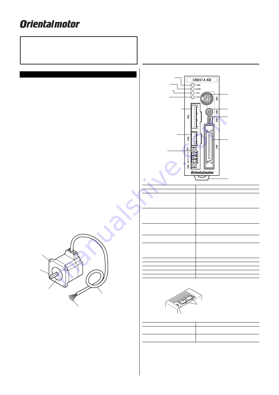
Names and functions of parts
●
Motor
Illustration shows the
PK56
type.
Motor cable
Motor lead wires
(5 pcs.: blue, red, orange, green, black)
Mounting hole
(4 locations)
Output shaft
Pilot
●
Front side of the driver
POWER LED (green)
Encoder connector (CN5)
Motor connector (CN4)
Power supply
connector (CN1)
C-ERR LED (red)
C-DAT LED (green)
ALARM LED (red)
Communication
connector (CN3)
Address number
setting switch (SW1)
Function setting
switches (SW2)
I/O signals
connector (CN2)
DIN lever
Name Description
POWER LED (green)
This LED is lit while the main power is input.
ALARM LED (red)
This LED will blink when an alarm generates
(a protective function is triggered). You can
check the generated alarm by counting the
number of times the LED blinks.
C-DAT LED (green)
This LED will blink or illuminate steadily
when the driver is communicating with the
master station properly via RS-485
communication.
C-ERR LED (red)
This LED will illuminate when a RS-485
communication error occurs with the master
station.
Address number setting switch
(SW1)
Set the address number of RS-485
communication.
Function setting switches (SW2)
No.1 to 3: Set the baud rate of RS-485
communication.
No.4: Set the address number of RS-485
communication with SW1.
Power supply connector (CN1)
Connect main power supply (+24 VDC).
I/O signals connector (CN2)
Connect I/O signals.
Communication connector (CN3)
Connect a data setter
OPX-2A
.
Motor connector (CN4)
Connect the motor.
Encoder connector (CN5)
Connect the encoder.
●
Upper side of the driver
Terminal resistor setting switch (SW3)
RS-485 communication
connector (CN6/CN7)
Name Description
Terminal resistor setting switch
(SW3)
Set the terminal resistor (120
Ω
) of RS-485
communication.
RS-485 communication connector
(CN6/CN7)
Connect the RS-485 communication cable.


