


2
Installation
Location for installation
The driver is designed and manufactured for installation in equipment.
Install it in a well-ventilated location that provides easy access for inspection.
The location must also satisfy the following conditions:
•
Inside an enclosure that is installed indoors (provide vent holes)
•
Operating ambient temperature
Motor: -10 to +50 °C (+14 to +122 °F) (non-freezing)
Driver: 0 to +40 °C (+32 to +104 °F) (non-freezing)
•
Operating ambient humidity 85% or less (non-condensing)
•
Area that is free of explosive atmosphere or toxic gas (such as sulfuric gas) or
liquid
•
Area not exposed to direct sun
•
Area free of excessive amount of dust, iron particles or the like
•
Area not subject to splashing water (rain, water droplets), oil (oil droplets) or
other liquids
•
Area free of excessive salt
•
Area not subject to continuous vibration or excessive shocks
•
Area free of excessive electromagnetic noise (from welders, power machinery,
etc.)
•
Area free of radioactive materials, magnetic fields or vacuum
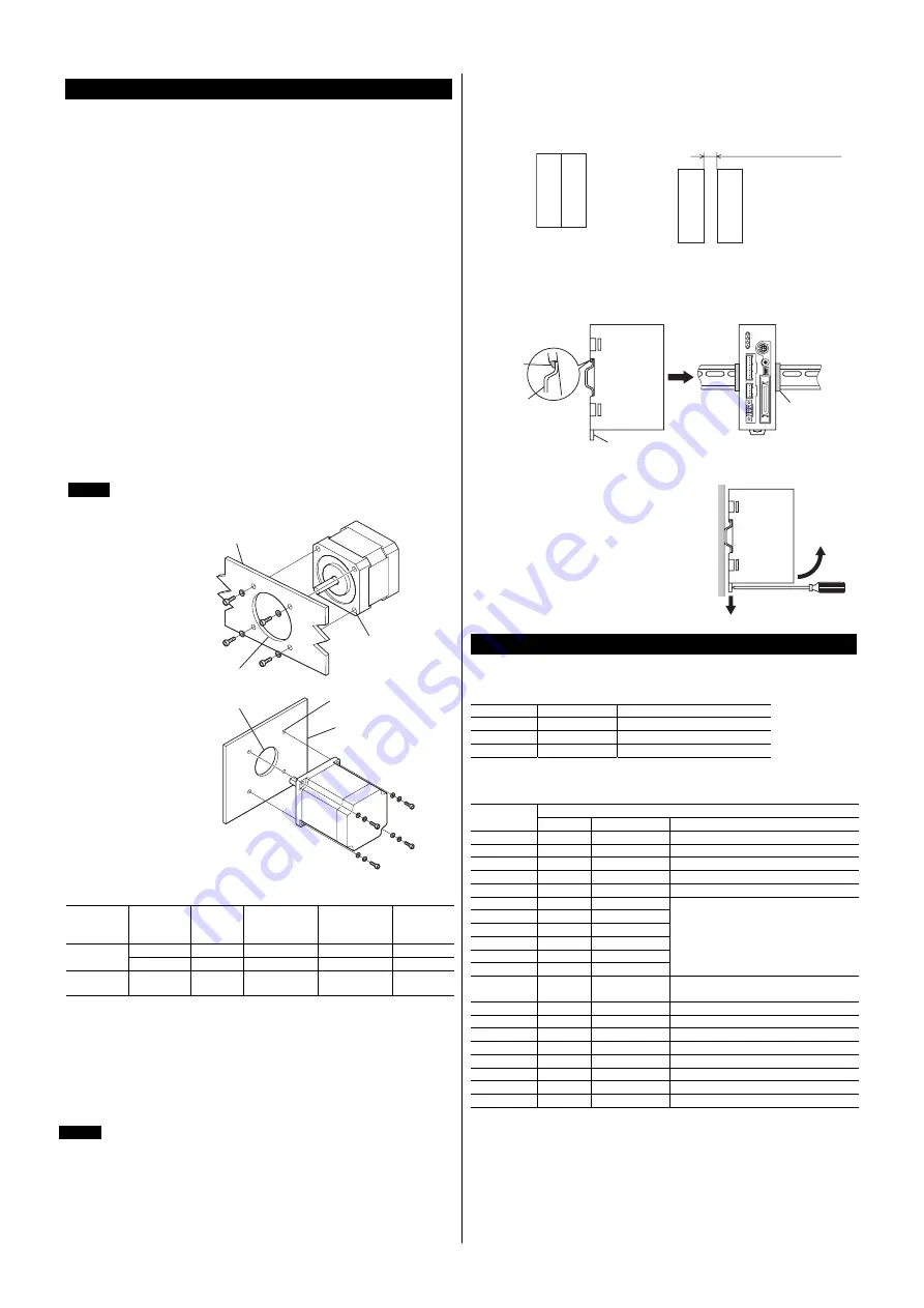
Installing the motor
The motor can be installed in any direction. Install the motor onto an appropriate
flat metal plate having excellent vibration resistance and heat conductivity.
When installing the motor, secure it with four bolts (not supplied) through the
four mounting holes. Do not leave a gap between the motor and metal plate.
Note
Insert the pilot located on the motor's installation surface into the
mounting plate's.
Installation method A
Pilot holder
Metal plate
Mounting
hole
Installation method B
Metal plate
Pilot holder
Mounting hole
Screw size, tightening torque and installation method
Motor type
Frame size
[mm (in.)]
Nominal
size
Tightening
torque
[N·m (oz-in)]
Effective
depth of bolt
[mm (in.)]
Installation
method
42 (1.65)
M3
1 (142)
4.5 (0.177)
A
Standard
60 (2.36)
M4
2 (280)
−
B
TH
geared
42 (1.65)
60 (2.36)
M4
2 (280)
8 (0.315)
A
Installing the driver
●
Installation direction
Use a DIN rail 35 mm (1.38 in.) wide to mount the driver. Provide 50 mm
(1.97 in.) clearances in the horizontal and vertical directions between the driver
and enclosure or other equipment within the enclosure.
Refer to the figure below for the required distances between adjacent drivers
when two or more drivers are installed in parallel.
Note
Be sure to install (position) the driver vertically. When the driver is
installed in any position other than vertical, the heat radiation effect of
the driver will drop.
•
CRD507-KD
Two or more
CRD507-KD
units can be
placed in contact with each other in the
horizontal direction. Provide a clearance
of 50 mm (1.97 in.) or more in the vertical
direction.
•
CRD514-KD
Provide a clearance of 20 mm (0.79 in.)
or more in the horizontal direction, and
50 mm (1.97 in.) or more in the vertical
direction.
20 mm (0.79 in.) or more
●
Installation method
Push up the driver’s DIN lever until it locks. Hang the hook at the rear to the DIN
rail, and push in the driver. After installation, fix the both sides of the driver with
the end plate.
Hook
DIN rail
DIN lever
End plate
Removing from DIN rail
Pull the DIN lever down until it locks using a
flat tip screwdriver, and lift the bottom of the
driver to remove it from the rail.Use a force of
about 10 to 20 N (2.2 to 4.5 lb.) to pull the DIN
lever down to lock it. Excessive force may
damage the DIN lever.
Pin assignments lists
CN1: Power supply connector
Connect using the supplied CN1 connector (3 pins).
Pin No.
Name
Description
1
+24 VDC
+24 VDC power supply input
2
GND
Power supply GND
3 FG
Frame
Ground
CN2: I/O signals connector
Connect using the supplied CN2 connector cable.
Upper ribbon cable
Lead wire
color
Pin No.
Signal name
Description
Brown-1 A1
IN-COM0 Input
common
Red-1 A2
START Start
input
Orange-1 A3
ALM-RST Alarm
reset
input
Yellow-1
A4
AWO
All windings off input
Green-1 A5
STOP
Stop
input
Blue-1 A6
M0
Purple-1 A7
M1
Gray-1 A8
M2
White-1 A9
M3
Black-1 A10
M4
Brown-2 A11
M5
Data selection input
Red-2 A12
HOME/
P-PRESET
Return-to-home/Position preset input
Orange-2 A13
FWD
Forward
input
Yellow-2 A14
RVS
Reverse
input
Green-2
A15
+LS
+ limit sensor input
Blue-2 A16
−
LS
−
limit sensor input
Purple-2
A17
HOMES
Mechanical home sensor input
Gray-2
A18
SLIT
Slit sensor input
White-2 A19
N.C.
Not
used
Black-2 A20
IN-COM1 Sensor
input
common


