2
y
Use a motor and driver only in the specified combination. Failure to
do so may result in fire.
y
Provide an emergency stop device or emergency stop circuit external
to the equipment so that the entire equipment will operate safely
in the event of a system failure or malfunction. Failure to do so may
result in injury.
y
Before supplying power to the driver, turn all input signals to the
driver to OFF. Failure to do so may result in injury or damage to
equipment.
y
Before moving the motor directly with the hands, confirm that the
AWO input turns ON. Failure to do so may result in injury.
y
When an abnormal condition has occurred, immediately stop
operation and turn off the driver power. Failure to do so may result in
fire or injury.
Precautions for use
•
When conducting the insulation resistance measurement and
the dielectric strength test, be sure to separate the connection
between the motor and the driver.
Conducting the insulation resistance test or dielectric strength test with the
motor and driver connected may result in damage to the product.
•
Regeneration
When a large load inertia is operated at a high speed, the power supply
voltage may increase by the regenerated energy generated, causing an
alarm of overvoltage to generate. This may result in damage to the driver, so
reconsider the operating condition so as not to generate the regenerative
voltage.
Preparation
Checking the product
Verify that the items listed below are included. Report any missing or
damaged items to the branch or sales office from which you purchased the
product.
y
Driver .........................................................1 unit
y
OPERATING MANUAL ..........................1 copy (this document)
y
Connector housing/contact .............1 set (Packed in a bag; see table below.)
Application
Housing (Molex)
Contact (Molex)
For power supply (CN1)
1 pc. 51103-0200 (2-poles)
19 pcs. 50351-8100
For motor (CN2)
1 pc. 51103-0500 (5-poles)
For I/O signals (CN3)
1 pc. 51103-1200 (12-poles)
When removing the driver from the ESD protection bag, make sure
your hands are not charged with static electricity. This is to prevent
damage to the driver due to static electricity.
How to identify the product model
CVD 5 18 B R - K SC
1
2
3
4
5
6
7
1
Driver type
CVD
:
CVD
driver
2
Number of phases of motor
5
: 5-phase
3
Motor rated current
12
: 1.2 A/phase
18
: 1.8 A/phase
24
: 2.4 A/phase
4
Driver shape
B
: With mounting plate
5
Connector shape
R
: Right angle
Blank: Standard
6
Power supply input
K
: DC power supply
7
Driver type
SC
: Speed control
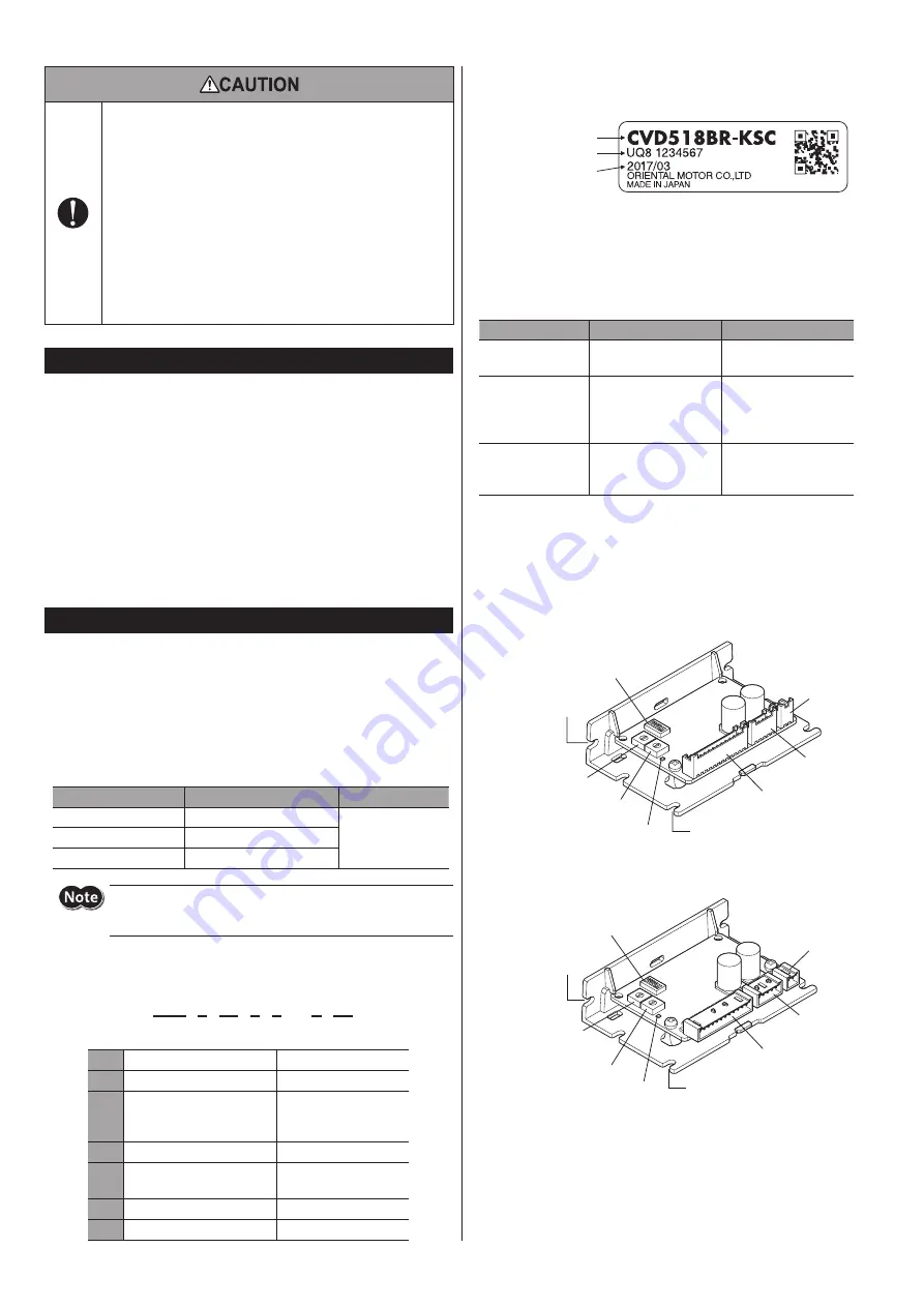
Information about nameplate
The figure shows an example.
Driver model
Serial number
Manufacturing date
Motor specifications for possible combinations
Use the
CVD
driver SC type in combination with the motors shown in the
table below.
Check the motor rated current on the Oriental Motor Website or the motor
nameplate.
Driver model *1
Motor rated current
Motor combination *2
CVD512B
-KSC
1.2 A/phae
PKP523N12
PKP525N12
CVD518B
-KSC
1.8 A/phae
PKP543N18
2
PKP544N18
2
PKP545N18
2
PKP546N18
2
CVD524B
-KSC
2.4 A/phae
PKP564FN24
2
PKP566FN24
2
PKP569FN24
2
*1 When the connector shape is of right angle,
in the model names indicates
R
.
*2
in the model names indicates
A
(single shaft) or
B
(double shaft)
representing the motor type.
Names of parts
z
When the connector shape is of standard
PWR/ALM LED
CN1 connector
(Power supply)
Cutout for mounting B
(2 places)
Cutout for mounting A (4 places)
CN2 connector
(Motor)
CN3 connector
(I/O signals)
×16/SPD1 switch
×1/SPD2 switch
Function setting switch
z
When the connector shape is of right angle
×16/SPD1 switch
×1/SPD2 switch
PWR/ALM LED
Function setting switch
CN1 connector
(Power supply)
CN2 connector
(Motor)
CN3 connector
(I/O signals)
Cutout for mounting B
(2 places)
Cutout for mounting A (4 places)


