5
Connection
For protection against electric shock, do not
turn on the power supply until the wiring is
completed.
Applicable connector
Type
Application
Model
Connector housing
For power supply (CN1)
51103-0200 (Molex)
For motor (CN2)
51103-0500 (Molex)
For I/O signals (CN3)
51103-1200 (Molex)
Contact
−
50351-8100 (Molex)
Designated crimping tool
−
63811-8100 (Molex)
Applicable lead wire
y
For power supply (CN1)
Stranded wire AWG22 (0.3 mm
2
)
Outer sheath diameter:
ø1.15 to 1.8 mm (ø0.045 to 0.071 in.)
Strip length of the insulation cover:
2.3 to 2.8 mm (0.091 to 0.11 in.)
y
For motor (CN2)
Stranded wire AWG24 to 22 (0.2 to 0.3 mm
2
) *
Outer sheath diameter:
ø1.15 to 1.8 mm (ø0.045 to 0.071 in.)
Strip length of the insulation cover:
2.3 to 2.8 mm (0.091 to 0.11 in.)
* AWG22 (0.3 mm
2
) for the
CVD524B
-KSC
y
For I/O signals (CN3)
Stranded wire AWG24 to 22 (0.2 to 0.3 mm
2
)
Outer sheath diameter:
ø1.15 to 1.8 mm (ø0.045 to 0.071 in.)
Strip length of the insulation cover:
2.3 to 2.8 mm (0.091 to 0.11 in.)
y
For the I/O signals cable, use a twisted pair cable.
y
Keep the wiring distance as short as possible [less than 2 m (6.6 ft.)] to
suppress the effect of noise.
y
A connection cable set is available as an accessory. Lead wires with a
connector allow for easy connection.
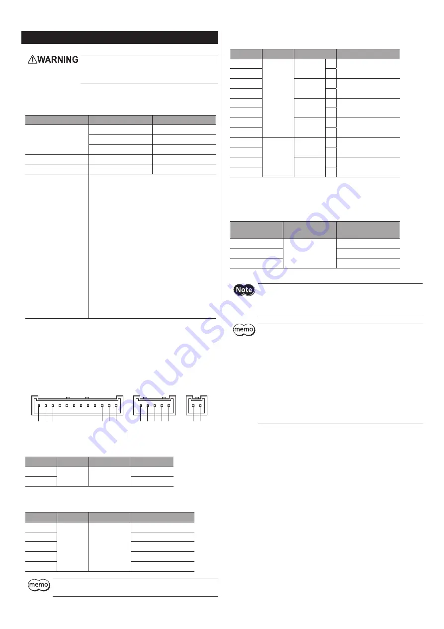
Connector pin assignment
1 2 3
• • • • • •
CN3
12
11
10
1 2
+ -
3 4 5
CN2
CN1
z
CN1 (Power supply)
Pin No.
Direction
Signal name
Description
+
Input
POWER
+24 VDC
−
GND
z
CN2 (Motor)
Pin No.
Direction
Signal name
Description
1
Output
MOTOR
Blue motor lead wire
2
Red motor lead wire
3
Orange motor lead wire
4
Green motor lead wire
5
Black motor lead wire
Connector pin assignments vary depending on the motor. For details,
refer to "Connecting the motor" on p.6.
z
CN3 (I/O signals)
Pin No.
Direction
Signal name
Description
1
Input
FWD
+
Forward input
2
−
3
RVS
+
Reverse input
4
−
5
AWO
+
All windings off input
6
−
7
M0
+
Data selection input
8
−
9
Output
ALM
+
Alarm output
10
−
11
PLS-OUT
+
Pulse output
12
−
Connecting the power supply
Use a power supply that can supply the following current capacity.
When the power is turned on, the PWR/ALM LED will be lit in green.
Driver model *
Input power supply
voltage
Power supply current
capacity
CVD512B
-KSC
+24 VDC±10%
0.9 A or more
CVD518B
-KSC
2.5 A or more
CVD524B
-KSC
3.0 A or more
* When the connector shape is of right angle,
in the model names indicates
R
.
y
When connecting, pay attention to the polarity of the power supply.
Reverse-polarity connection may cause damage to the driver.
y
Have the connector plugged in securely. Insecure connection may
cause malfunction or damage to the motor and driver.
y
When unplugging the connector, do so while spreading the latches
on the connector a little.
y
When cycling the power or plugging/unplugging the connector,
turn off the power and wait for the PWR/ALM LED to turn off.
y
Separate I/O signals cable at least 100 mm (3.94 in.) from
electromagnetic relays and other than inductance loads.
Additionally, route I/O signals cable perpendicular to power supply
cable and motor cable, rather than in a parallel fashion.
y
Do not route the power supply cable in the same conduits as other
power supply lines and motor cable.
y
If the motor cable or power supply cable generates an undesirable
amount of noise depending on the wiring or configuration, shield
the cable or install a ferrite core.


