2
Preparation
Checkingtheproduct
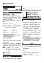
Verify that the items listed below are included. Report any missing or
damaged items to the branch or sales office from which you purchased the
product.
Brakeypackyyyy1yunit
Flush-mountingysocketyyyy1ypiece
MODEL
SB50W
POWER
ALARM
1-40
W
60-90W
Operatingymanualyyyy1ycopy
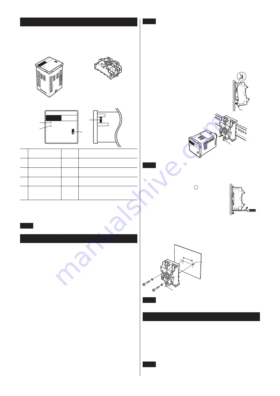
Namesandfunctionsofparts
POWER
ALARM
MODEL
SB50W
1-40W
60-90W
SINK
SOURCE
①
②
③
④
No.
Name
Factoryy
setting
Description
①
POWERyindicator
(green)
–
Litywheny24yVDCyisysupplied.
②
ALARMyindicator
(red)
–
LitywhenytheyALARMyoutputyisy
"OFF."
③
Motoryoutput
selectoryswitch
60-90yW Changeytheysettingyofythisyswitchy
accordingytoytheymotoryoutput.
④
Sink/Source
selectoryswitch
SINK
Switchytheycontrolysignalyinput/
outputymodeybetweeny"sinkylogic"y
andy"sourceylogic"y(pagey3).
Applicablemotors
K
Ⅱ
series,
V
series, World
K
series,
FPW
series,
K
series (motor output 1 to 90 W except for the 2-pole type)
Note
Three-phaseymotorsycannotybeyusedyinycombination.
Installation
This section covers the environment and method of installing the brake pack.
Locationforinstallation
Install it in a well-ventilated location that provides easy access for inspection.
The location must also satisfy the following conditions:
y
Inside an enclosure that is installed indoors (provide vent holes)
y
Operating ambient temperature 0 to +40 °C (+32 to +104 °F) (non-freezing)
y
Operating ambient humidity 85% or less (non-condensing)
y
Area that is free of explosive atmosphere or toxic gas (such as sulfuric gas)
or liquid
y
Area not exposed to direct sun
y
Area free of excessive amount dust, iron particles or the like
y
Area not subject to splashing water (storms, water droplets), oil (oil
droplets) or other liquids
y
Area free of excessive salt
y
Area not subject to continuous vibration or excessive shocks
y
Area free of excessive electromagnetic noise (from welders, power
machinery, etc.)
y
Area free of radioactive materials, magnetic fields or vacuum
y
Altitude: Up to 1000 m (3300 ft.) above sea level
Howtoinstallthemotioninterface
The brake pack has been designed on the basis of heat dissipation through air
convection.
Install the brake pack on a metal plate having a high degree of vibration
resistance.
In the presence of a great amount of vibration, do not use a DIN rail. Screw
down the brake pack directly through the use of a flush-mounting socket.
Note
y
•
Thereymustybeyayclearanceyofyatyleasty25ymmy(0.984yin.)yandy
50ymmy(1.97yin.)yinytheyhorizontalyandyverticalydirections,y
respectively,ybetweenytheybrakeypackyandyenclosureyory
otheryequipmentywithinytheyenclosure.
y
•
Doynotyinstallynearytheybrakeypackyanyyequipmentythaty
generatesyaylargeyamountyofyheat.
y
•
Checkyventilationyifytheyambientytemperatureyofytheybrakey
packyexceedsy40y°Cy(104y°F).
z
MountingtoDINrail
Use a DIN rail 35 mm (1.38 in.) wide to mount the flush-mounting socket.
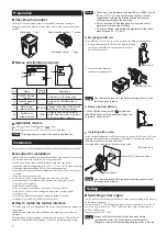
1. Engage the hooks on the back of the flush-mounting
socket over the DIN rail, then push the DIN lever
until it locks in place.
DIN lever
2. Insert the brake pack into
the flush-mounting socket.
MO
DEL
SB50W
POWER
ALARM
Mounting hook
1-4
0W
60
-90W
Note
Useytheymountingyhookyofytheyflush-mountingysocketytoylocky
theybrakeypackyinyplace.
z
RemovingfromDINrail
PullytheyDINyleverydownywithyayy–yyscrewdriver,yy
thenyliftytheybottomyofytheyflush-mountingysocketyy
toyremoveyityfromytheyrail.
z
Installingwithscrews
Install the flush-mounting socket by securing it with two bolts (M4 or M3, not
supplied) through the two mounting holes provided. Leave no gap between
the flush-mounting socket and metal plate.
Insert the brake pack into the flush-mounting socket.
2×Ø4.5 (Ø0.177) Mounting holes
40
r
0.2
(1.57
r
0.008
)
Mounting hook
[Unitymmy(in.)]
Note
Useytheymountingyhookyofytheyflush-mountingysocketytoylocky
theybrakeypackyinyplace.
Setting
Switchingmotoroutput
Set the motor output selector switch on the brake pack according to the output
of the motor connected.
Set the switch to "1 - 40 W" when the brake pack is connected to a 1 to 40 W
motor. Set the switch to "60 - 90 W" when the brake pack is connected to a
60 W or 90 W motor.
Factory setting is "60 - 90 W."
Note
Alwaysysetytheymotoryoutputytoytheybrakeypackybeforey
operatingytheymotor.yTheybrakeypackywillynotyacceptyanyy
changesytoytheymotoryoutputysettingywhileytheymotoryisyrunning.

