3
Connection
This section covers the methods and examples of connecting the brake pack,
power, motor and external controller, as well as the input/output signals.
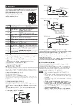
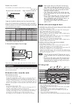
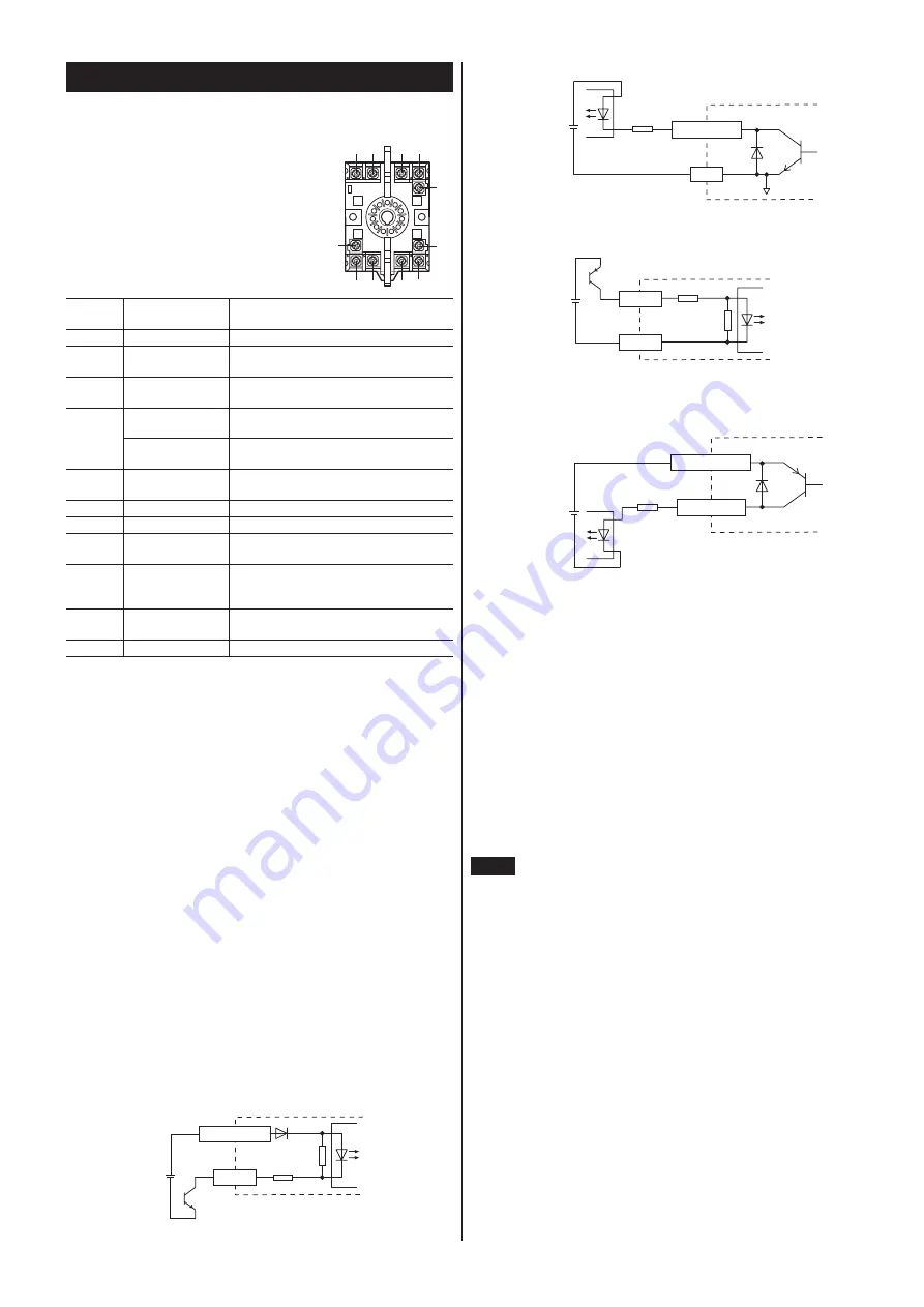
Terminalassignments
The following figure shows the terminal
assignments. The terminals of the socket are
marked with terminal numbers.
2
3
1
11
9
10
5
4
6
7
8
⑧ ⑦
⑥ ⑤
⑩ ⑪
① ②
③
④
⑨
Terminal
No.
Signalyname
Description
①
Motor/capacitor
Connectytheymotoryandycapacitor.
②
ACypoweryinputy
(L)
Single-phasey100y-y115yVyoryy
single-phasey200y-y230yV
③
NC
Notyused.y
Leaveythisyterminalyunconnected.
④
∗
1
Brakeyreleasey
inputy
∗
2
Notyanyinstantaneousystopybutyaynaturaly
stop.
ALARM-RESETy
input
ResetytheyALARMyoutput.
⑤
CCWyoperationy
inputy
∗
3
MotoryrunsyinytheyCCWydirectionyduringy
"ON."
⑥
DCypoweryinput
+24yVDCyinput
⑦
GND
GND
⑧
CWyoperationy
input
MotoryrunsyinytheyCWydirectionyduringy
"ON."
⑨
ALARMyoutputy
∗
4
Turnsy"OFF"yunderycertainyconditionsy
suchyasywhenytheymotor’sythermaly
protectorybecomesy"open."
⑩
Electromagneticy
brakey
∗
5
Connectytoytheyelectromagneticybrake.
⑪
Motor/capacitor
Connectytheymotoryandycapacitor.
*1 This signal functions as the brake release input during normal operation,
and as the ALARM-RESET input when the ALARM output is OFF.
(Refer to "Resetting an ALARM" on page 6.)
*2 Releases the electromagnetic brake for the motor with electromagnetic
brake.
*3 Not applicable to an induction motor which has four lead wires.
*4 For details, check "ALARM output" on page 6.
*5 Only for electromagnetic-brake motors.
Input/outputsignals
The input/output circuits are initially set to sink logic. Switch the circuit mode
between "sink logic" and "source logic" according to the external control
equipment used. (Refer to "Switching between sink logic and source logic.")
z
Inputcircuit(internalcircuit)
The input-signal voltage is 24 VDC.
Input signals are provided as photocoupler inputs.
The signal state indicates the "ON: current supplied" or "OFF: current not
supplied" status of the internal photocoupler rather than the voltage level of
the signal.
z
Outputcircuit(internalcircuit)
Output signals are provided as open-collector outputs.
The signal state indicates the "ON: current supplied" or "OFF: current not
supplied" status of the internal transistor rather than the voltage level of the
signal.
Use a power source of 26.4 VDC or less, and limit the output current to
10 mA or less.
y
•
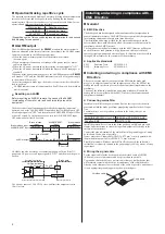
Connectionyexampleyofysinkylogic
DC power input
24 VDC
Brake pack
Input
䈜
4.7 k
Ω
560
Ω
䈜㻌䐦
CW operation input
㻌 䐣
CCW operation input
㻌 䐢
Brake release input
Input circuit
䐤
ALARM output
Brake pack
GND
䐧
䐥
0 V
Output circuit
2.7 k
Ω
or more
24 VDC
y
•
Connectionyexampleyofysourceylogic
24 VDC
Brake pack
䈜㻌䐦
CW operation input
㻌 䐣
CCW operation input
㻌 䐢
Brake release input
Input
GND
4.7 k
Ω
560
Ω
Input circuit
䐥
䈜
Brake pack
ALARM output
䐤
䐧
DC power input
24 VDC
Output circuit
2.7 k
Ω
or more
z
Switchingbetweensinklogicandsourcelogic
Use the sink/source selector switch on the side of the brake pack to switch the
input/output circuit mode between "sink logic" and "source logic."
In an input circuit of sink logic, a signal turns ON when current flows out of
the applicable input terminal.
In an input circuit of souce logic, a signal turns ON when current flows into
the applicable input terminal.
The factory setting is sink logic. Set an appropriate mode after confirming the
output circuit of the external control equipment to be used.
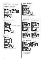
Connectionexample
The connection example of page 4 is for sink logic. See page 5, for the
connection example of source logic.
The direction of motor rotation indicates the direction as viewed from the
output-shaft side. "CW" indicates clockwise and "CCW"counterclockwise.
The direction of gear-output shaft rotation may be opposite that of motor
rotation, depending on the gear ratio of the gear head.
Note
y
•
Theyinput-signalyvoltageyisy24yVDC±10%yandy0.1yAyory
more.
y
•
Keepytheypowerylineyforytheybrakeypackyawayyfromythatyofy
noiseysourcesysuchyasyweldersyandymachinesydischargingy
electricity.
y
•
Minimizeytheylengthyofytheymotorycableyandytheyinput/outputy
signalycable.
y
•
Wireytheyinput/outputysignalycablesysoythatytheyyareyaty
leasty300ymmy(11.8yin.)yawayyfromycablesycarryingyaylargey
amountyofycurrent.yLetytheypowerycableyandymotorycabley
crossyatyay90-degreeyangleyinsteadyofyusingyparallelywiring.
y
•
UseyaycableyofyAWG18y(0.75ymm
2
)yorymoreyinydiameteryfory
theymotorycableyandypowerycable.
y
•
BeysureytoyconnectytheyGNDyterminalytoyGNDy(negativey
side)yofytheyexternalycontroller,yorytheyunitywillynotyoperate.

