5
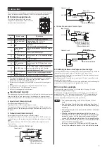
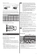
Suitableycrimpyterminal
Use insulated crimp terminals, as shown below, for connection.
[Unit:ymmy(in.)]
Ringytypeyterminalywithyinsulation
Uytypeyterminalywithyinsulation
Ø3.7 (Ø0.146) or more
7.6 (0.299) or les
s
9 (0.354) or more
9 (0.354) or more
3.7 (0.146) or more
7.6 (0.299) or les
s
Capacityyofyprotectionydevicesy(suchyasycircuityprotectors)
When a motor is stopped suddenly, a large half-wave rectified current flows
through the motor for 0.2 to 0.4 seconds. When connecting a protective device
such as a circuit protector to the motor, refer to the table below for the braking
current and select its current capacity.
Motoryoutputypower
Brakingycurrenty[A]y(Peakyvalue)
100yV/110yV/115yV
200yV/220yV/230yV
1yW
1.0
0.3y
∗
6yW
1.6
1.0
15yW
5.3
2.5
25yW
9.7
4.4
40yW
16
8.2
60yW
23
12
90yW
34
17
∗
In case of power-supply voltage is 200 V.
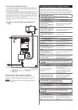
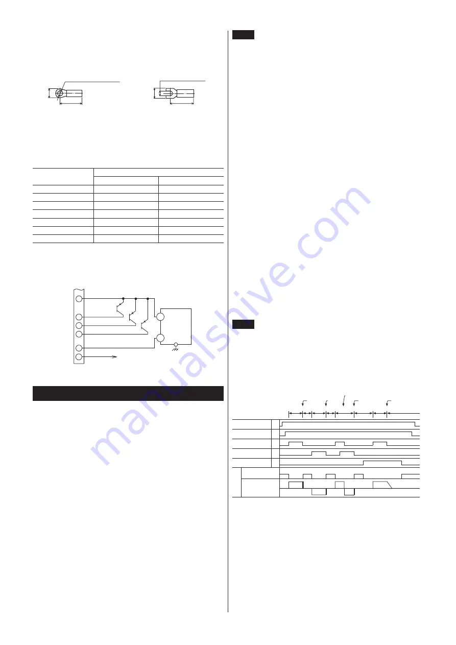
z
Connectionexampleofsourcelogic
9
ALARM output
6
8
4
7
5
CCW operation input
+24 V
CW operation
input
Brake pack
terminal No.
GND
Brake release input
24 VDC
0.1 A or more
+
-
FG
Connections to the AC power supply and motor conform to the sink logic.
Operation
This section covers the methods of operating and (instantaneously) stopping a
motor using the brake pack.
Inductionmotor,reversiblemotor
Start/instantaneousystop
• Set the brake release input to "OFF."
• Turning CW operation input to "ON" will operate the motor in the CW
direction, while turning it to "OFF" will trigger an instantaneous stop.
• Turning CCW operation input to "ON" will operate the motor in the CCW
direction, while turning it to "OFF" will trigger an instantaneous stop. This
function is not applicable to an induction motor which has four lead wires.
Start/stop
• Set the brake release input to "ON."
• Turning CW operation input to "ON" will operate the motor in the CW
direction, while turning it to "OFF" will stop the motor.
• Turning CCW operation input to "ON" will operate the motor in the CCW
direction, while turning it to "OFF" will stop the motor. This function is
not applicable to an induction motor which has four lead wires.
The stopping time varies, depending on its inertial and frictional loads.
Note
y
•
Whenyanyinductionymotorywhichyhasyfouryleadywiresyisy
toybeystartedyory(instantaneously)ystoppedyinytheyCCWy
direction,ybeysureytoychangeytheymotor’syleadyconnections.
y
•
Anyinductionymotorymustybeycompletelyystoppedybeforey
switchingyitsydirectionyofyrotation.
y
•
IfytheyCWyoperationyinputyandyCCWyoperationyinputyarey
setytoy"ON"ysimultaneously,ytheyCWyoperationyinputywillybey
givenypriority
y
•
DoynotysetytheyCWyoperationyinput,yCCWyoperationyinputy
orybrakeyreleaseyinputytoyONybeforeyturningyonytheyACy
power.ySettingytheseyinputsytoyONybeforeyturningyonythey
ACypowerywillynotyenableymotoryoperation.y
AnyALARMyindicatorywillylightyandyALARMyoutputywilly
switchytoy"OFF."
Motorwithelectromagneticbrake
Start/instantaneousystopywithytheyelectromagneticybrakeyenabled
• Set the brake release input to "OFF."
• Turning CW operation input to "ON" will "release" the electromagnetic
brake and operate the motor in the CW direction.
Turning it to "OFF" will trigger an instantaneous stop.
The electromagnetic brake will be "activated" in order to hold the load in
position the moment the motor stops.
• Turning CCW operation input to "ON" will "release" the electromagnetic
brake and operate the motor in the CCW direction.
Turning it to "OFF" will trigger an instantaneous stop.
The electromagnetic brake will be "activated" in order to hold the load in
position the moment the motor stops.
Start/stopywithytheyelectromagneticybrakeydisabled
• Set the brake release input to "ON."
• Turning CW operation input to "ON" will operate the motor in the CW
direction, while turning it to "OFF" will stop the motor.
• Turning CCW operation input to "ON" will operate the motor in the CCW
direction, while turning it to "OFF" will stop the motor.
Setting the brake release input to "ON" will "release" the electromagnetic
brake. To move the load of the motor with electromagnetic brake manually,
set the brake-release input to "ON."
Note
y
•
IfytheyCWyoperationyinputyandyCCWyoperationyinputyareysety
toy"ON"ysimultaneously,ytheyCWyoperationyinputywillybeygiveny
priority.
y
•
DoynotysetytheyCWyoperationyinput,yCCWyoperationyinputyory
brakeyreleaseyinputytoyONybeforeyturningyonytheyACypower.y
SettingytheseyinputsytoyONybeforeyturningyonytheyACypowery
willynotyenableymotoryoperation.
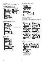
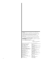
Timingchart
AC power supply
ON
OFF
CW operation input
ON
OFF
CCW operation input
ON
OFF
ON
OFF
CW
CCW
CW
CCW
CW
Stop
Stop
Stop
Stop
Operation
Operation
Operation
Operation
Brake release input
Electromagnetic
brake
Clockwise
rotation
Movement
Counterclockwise
rotation
Motor
DC power supply
ON
OFF
∗
4
∗
1
∗
3
∗
1 Do not set the CW operation input, CCW operation input or brake release
input to ON before turning on the AC power.
Setting these inputs to ON before turning on the AC power will not enable
motor operation.
ޓ
An ALARM indicator will light and ALARM output will switch to "OFF."
∗
2 The brake release input serves as the ALARM-RESET input when the
ALARM output is OFF.
∗
3 Only for motor with electromagnetic brake
∗
4 The induction motor will not accommodate instantaneous forward/reverse switching.
Natural stop
Braking
Braking
Braking
Reversing
Holding
Holding
Holding
Holding
Holding
∗
1
∗
1
∗
2


