7
z
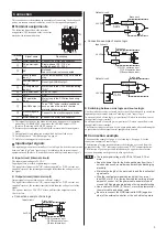
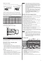
Notesaboutinstallationandwiring
y
Connect the motor/brake pack and other peripheral control equipment
directly to the grounding point so as to prevent a potential difference from
developing between grounds.
y
When relays or electromagnetic switches are used together with the system,
use mains filters and CR circuits to suppress surges generated by them.
y
Keep cables as short as possible without coiling and bundling extra lengths.
y
Place the power cables such as the motor and power-supply cables as far
apart [100 to 200 mm (3.94 to 7.87 in.)] as possible from the signal cables.
If they have to cross, cross them at a right angle.
Place the AC input cable and output cable of a mains filter separately from
each other.
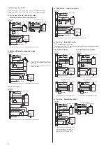
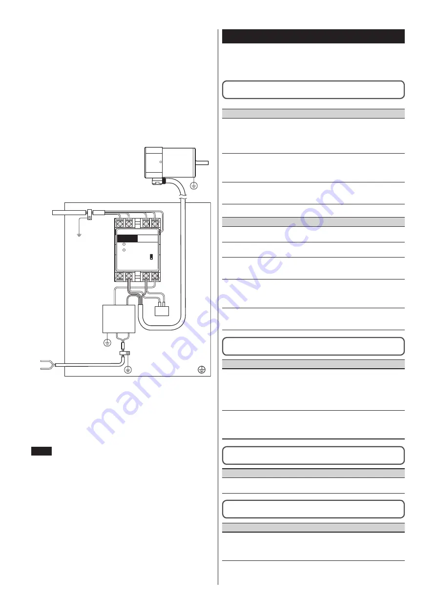
z
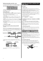
Exampleofmotorandbrakepackinstallationand
wiring
POWER
ALARM
L
N
C
A
A
E
B
D
Motor
Capacitor
Power input
Grounded Panel
D: Motor cable [10 m (32.8 ft.)]
E: Mains filter
MODEL
SB50W
1-40W
60-90W
A: Cable clamp
B: Signal cable [2 m (6.6 ft.)]
C: Power cable
Precautionsaboutstaticelectricity
Static electricity may cause the brake pack to malfunction or become
damaged. Be careful when handling the brake pack with the power on.
Note
Doynotycomeycloseytoyorytouchytheybrakeypackywhileythey
poweryisyon.
Troubleshootingandremedialactions
During motor operation, the motor or brake pack may fail to function
properly due to an improper signal input method or wiring. When the motor
cannot be operated correctly, refer to the contents provided in this section and
take appropriate action. If the problem persists, contact your nearest office.
The motor does not run.
The number of motor rotations per minute is too low.
y
•
TheyALARMyindicatoryisylit.
Possibleycause
Remedial action
Theymotor’sythermalyprotectory
hasybeenyactuated.
(onlyyforyaymotoryequippedywithy
aythermalyprotectoryofy15yWyory
largerycapacity)
Remove the cause of motor overheating,
then reset an ALARM after the motor
TheyCWyoperationyinput,yCCWy
operationyinputyorybrakeyreleasey
inputywasysetytoy"ON"ybeforey
turningyonytheyACypower.
Set the applicable input signal to "ON"
after turning on the AC power.
Theypowerycableyorymotorycabley
isynotyconnectedyproperlyyory
broken.
Check the connection.
y
•
TheyALARMyindicatoryisynotylit.
Possibleycause
Remedial action
Theycapacitoryisyincorrectlyy
connected.
Reconnect the capacitor correctly.
CWyoryCCWyoperationyinputyisy
notyturnedytoy"ON."
Check the state or connection of CW and
CCW operation inputs.
Theypowerycableyorymotorycabley
isynotyconnectedyproperlyyory
broken.
Check the connection.
Theyelectromagneticybrakeyisy
incorrectlyyconnected.
(forytheyelectromagnetic-brakey
typeyonly)
Reconnect the electromagnetic brake
correctly.
Theysink/sourceyselectoryswitchy
isynotysetycorrectly.
Set the sink/source selector switch
according to the external control
The motor rotates in the direction opposite that which is
specified.
Possibleycause
Remedial action
CWyoryCCWyoperationyinputy
isyincorrectoryhasyaybady
connection.
Check the state or connection of CW and
CCW operation inputs.
The motor rotates in the CW direction
when CW operation input is "ON,"
and in the CCW direction when CCW
operation input is "ON."
Theygear-outputyshaftyrotatesy
inytheydirectionyoppositeymotory
rotationyatycertainygearyratios.
If the motor gear ratio makes the shaft
rotate in the direction opposite motor
rotation, reverse the operation for CW
and CCW operation inputs.
The motor does not stop instantaneously.
The electromagnetic brake does not hold.
Possibleycause
Remedial action
Brakeyreleaseyinputyisysetytoy
"ON."
Set brake release input to "OFF."
The ALARM is not reset even after the AC power was
turned off.
Possibleycause
Remedial action
TheyDCypoweryisynotyturnedyoffy
orynotyallyinputysignalsyareysetytoy
OFF.
To reset an ALARM, turn off the AC
power and DC power, set all signal
inputs to "OFF," and then turn the power
back on.


