
6
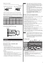
Operation/brakingrepetitivecycle
The repeated operation and braking of a motor will bring about a temperature
increase in the motor and brake pack, thereby limiting the continuous
operating time. Observe the repetitive cycle given in the table below for the
operation and braking of the motion interface.
Motoryoutput
Repetitionycycle
1ytoy25yW
2ysecondsyorymore
40ytoy90yW
4ysecondsyorymore
(Ayrepetitiveycycleyofytwoysecondsyrepresentsyoperationyforyoneysecondy
andystoppingyforyoneysecond.)
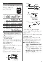
ALARMoutput
The ALARM output function of the
SB50W
monitors the motor current to
detect an actuation of the thermal protector. Accordingly, the ALARM output
function is activated in the following conditions:
y
When the built-in thermal protector of the motor was actuated
(became open).
y
When an improper connection or breakage of the power cable or motor
cable was detected.
y
When the AC power was turned on after setting an input signal to "ON."
y
When the AC power was turned off while the motor was still running or at
standstill.
When any of the above conditions occurs, the ALARM output of the
SB50W
will become "OFF" and the ALARM indicator (red) will be lit (power supply
to the motor will be cut off).
In the electromagnetic-brake type, the brake is activated in order to hold the
load in position.
∗
ALARM indicator lamp is lit momentarily when DC power is first turned on,
which is normal.
z
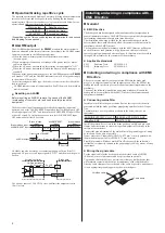
ResettinganALARM
BeforeyresettingyanyALARM,yremoveytheycauseyofytheyALARMy
(overheatingyofytheymotor,yetc.)yandyconfirmysafetyyaroundythey
equipment.
The brake release input functions as the brake release input during normal
operation, and as the ALARM-RESET input when the ALARM output is OFF.
Set all input signals to "OFF," and then turn the ALARM-RESET input ON for
at least 0.5 second. To restart the operation, turn the ALARM-RESET input
OFF and wait for at least 0.5 second.
Brake release input
/
ALARM-RESET input
ALARM output
0.5 s
or more
ON or OFF
0.5 s
or more
ON or OFF
Brake release
input
ALARM-RESET
input
Brake release
input
ON
ON
ALARM reset
0.5 s or less
Turns
OFF when an
ALARM is generated.
Occurrence of ALARM
ON
ALARMs can also be reset by reconnecting the power. Turn off the DC
power and AC power, set all input signals to "OFF," and then turn the power
back on.
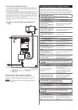
Limiting resistance
2.7 k
Ω
or more
24 VDC
External controller
Brake pack
GND
ALARM output
⑦
⑨
Photocoupler
Use a power source of 26.4 VDC or less, and limit the output current to
10 mA or less.
Installingandwiringincompliancewith
EMCDirective
General
z
EMCDirective
The brake pack has been designed and manufactured for incorporation in
general industrial machinery. The EMC Directive requires that the equipment
incorporating this product comply with these directives.
The installation and wiring method for the motor and brake pack are the
basic methods that would effectively allow the customer’s equipment to be
compliant with the EMC Directive.
The compliance of the final machinery with the EMC Directive will depend
on such factors as configuration, wiring, layout and risk involved in the
control-system equipment and electrical parts. It, therefore, must be verified
through EMC measures by the customer of the machinery.
z
Applicablestandards
EMI
Emission Tests
EN 61000-6-4
EMS
Immunity Tests
EN 61000-6-2
InstallingandwiringincompliancewithEMC
Directive
Effective measures must be taken against the EMI that the brake pack
may give to adjacent control-system equipment, as well as the EMS of the
brake pack itself, in order to prevent a serious functional impediment in the
machinery.
The use of the following installation and wiring methods will enable the
brake pack to be compliant with the EMC Directive (the aforementioned
compliance standards).
z
Connectingmainsfilter
Install a mains filter in the power source line in order to prevent the noise
generated within the brake pack from propagating outside via the AC input
line.
For mains filters, use the products as shown in the below chart, or an
equivalent.
SOSHINyELECTRICyCO.,LTD HF2010A-UPF,yNF2010A-UP
SchaffneryEMC
FN2070-10-06
Install the mains filter as close to the brake pack as possible, and use cable
clamps and other means to secure the input and output cables firmly to the
surface of the enclosure.
Connect the ground terminal of the mains filter to the grounding point, using
as thick and short a wire as possible.
Do not place the AC input cable (AWG18: 0.75 mm
2
or more) parallel with
the mains-filter output cable (AWG18: 0.75 mm
2
or more).
Parallel placement will reduce mains-filter effectiveness if the enclosure’s
internal noise is directly coupled to the power-supply cable by means of stray
capacitance.
z
Wiringthesignalcable
For the signal cable for the brake pack, use a shielded cable of AWG28
(0.08 mm
2
) or more in diameter, and keep it as short as possible.
To ground a shielded cable, use a metal cable clamp or similar device that
will maintain contact with the entire circumference of the shielded cable.
Attach a cable clamp as close to the end of the cable as possible, and connect
it to an appropriate grounding point as shown in the figure.
Cable clamp
Shielded cable


