background image

Professional Collection Manual 

What’s Included 

SPECIFICATIONS 

2

MODEL*

PP80B, PP80W

PP60B, PP60W

PP50B, PP50W

PART

SPP80000B, SPP80000W

SPP60000B, SPP60000B

SPP50000B, SPP50000W

Woofer

8” (203mm) Polypropylene

61/2” (165mm) Polypropylene 5 1/4” (133mm) Polypropylene

Tweeter 

1” (25mm) Silk DSPD™ MMP™  1” (25mm) Silk DSPD™ MMP™ 1” (25mm) Silk DSPD™ MMP™

Power Handling 

(Continuous Program Power)

200 Watts

130 Watts

100 Watts

Power Handling 

(Continuous Pink Noise)

100 Watts

65 Watts

50 Watts

Frequency Response (+/- 10dB)

42Hz-20kHz

50Hz-20kHz

57Hz-20kHz

Frequency Response (+/- 3dB)

57Hz-20kHz

62Hz-20kHz

75Hz-20kHz

Nominal Coverage Angle

110 Degree Conical Coverage 120 Degree Conical Coverage 120 Degree Conical Coverage

Rated Maximum SPL @1m

110dB

108dB

105dB

Rated Impedance

8 Ohm nominal

8 Ohm nominal

8 Ohm nominal

Transformer Taps

70V - 60W, 30W, 15W, 7.5W

100V - 60W, 30W, 15W

70V - 60W, 30W, 15W, 7.5W

100V - 60W, 30W, 15W

70V - 30W, 15W, 7.5W, 3.75W

100V - 30W, 15W, 7.5W

Diameter 

10” (254mm)

8 1/4” (210mm)

 6 11/16” (170mm)

Length

16 1/4” (412mm)

12 5/16” (313mm)

10 1/2” (267mm)

Feature 1 

8” Passive Radiator 

6 1/2” Passive Radiator

5” Passive Radiator

MODEL

PBR68B, PBR68W

PART

PBR68000B, PBR68000W

Rated Impedance

8 ohm nominal

Transformer Taps

70V - 60W, 30W, 15W,7.5W

100V - 60W, 30W, 15W

Diameter 

10” (254mm)

Length

13 1/2” (342mm)

MODEL*

PPSUB8B, PPSUB8W

PART

SPPSUB80B, SPPSUB80W

Woofer 

8” (203mm) Polypropylene

Power Handling 

(Continuous Program Power)

200 Watts

Power Handling 

(Continuous Pink Noise)

125 Watts

Frequency Response (+/- 10dB)

40Hz-250Hz

Frequency Response (+/- 3dB)

55Hz-250Hz

Nominal Coverage Angle

180 Degree Conical Coverage

Rated Maximum SPL @1m

110dB

Rated Impedance

8 Ohm nominal

Transformer Taps

70V -120W, 60W, 30W, 15W

100V - 120W, 60W, 30W

Diameter 

10” (254mm)

Length

16 1/4” (412mm)

Feature 1 

8” Passive Radiator

• Speaker
• Grille Removal Key
• Gripple® Suspension Kit Containing: 
   • Gripple Rope Grip (2)
   • Gripple Release Key
   • Hanging Cable (stainless steel)
   • Safety Cable (stainless steel)
• Cable Ties (3)
• Installation Manual

* All models:
• Available in black and white colors.
•  Gripple® Suspension Kit safe working load
    = 100lbs/45Kg Max

*All product information is subject to change. Please refer to the dealer portal for the latest information.

Summary of Contents for PP50B

Page 1: ...PP50 PPSUB8 PP80 PP60 Installation Manual PROFESSIONAL COLLECTION Pendant Speakers PP50B PP60B PP80 PPSUB8B PBR68B PP50W PP60W PP80W PPSUB8W PBR68W PBR68 MPP01 REV0 ...

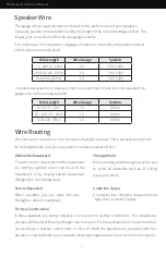
Page 2: ...troduction 1 Certifications Safety Agency 1 What s Included 2 Specifications 2 Product Features 3 70v 100v System 4 Speaker Placement 5 Speaker Wire 6 Wire Routing 6 Installation 7 Troubleshooting 12 Technical Assistance 12 Warranty 13 Return Process 13 ...

Page 3: ...ation questions please call us at 844 674 4461 Hours of operation are 8 00am to 5 00pm Pacific Time Monday through Friday 1 Introduction Certifications SAFETY AGENCY COMPLIANCE Origin Acoustics Professional Collection Pendant speakers models PP50 PP60 PP80 PPSUB8 meet the following standards UL 1480A Standard for Speakers for Commercial and Professional Use NFPA 70 The installation methods should ...

Page 4: ...gth 16 1 4 412mm 12 5 16 313mm 10 1 2 267mm Feature 1 8 Passive Radiator 6 1 2 Passive Radiator 5 Passive Radiator MODEL PBR68B PBR68W PART PBR68000B PBR68000W Rated Impedance 8 ohmnominal Transformer Taps 70V 60W 30W 15W 7 5W 100V 60W 30W 15W Diameter 10 254mm Length 13 1 2 342mm MODEL PPSUB8B PPSUB8W PART SPPSUB80B SPPSUB80W Woofer 8 203mm Polypropylene Power Handling Continuous Program Power 20...

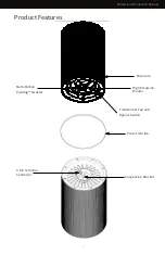
Page 5: ...ap and Bypass Switch Enclosure 4 Pin Terminal Connector Suspension Bracket Press Fit Grille Multi Motion Pivoting Tweeter 3 PP80 views SCALE 1 2 Origin Acoustics 6975 S Decatur Blvd Suite 140 Las Vegas NV 89118 844 ORIGIN1 674 4461 www originacoustics com A C O U S T I C S O R I G I N ...

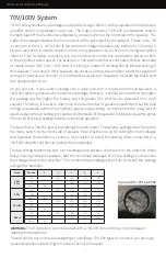
Page 6: ... be delivered from each speaker Therefore it is best to determine the total number of speakers needed and set the taps as high as possible within the amplifier s power output rating As mentioned the rotary switch used to adjust the tap setting is located at the front side of the speaker It is best to leave the grilles off until all of the tap settings have been properly adjusted The table below li...

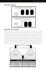
Page 7: ... be possible Also realize that the higher the ceiling the greater the conical dispersion and therefore the larger coverage area per speaker The further the speaker is from the listener the lower the SPL As the speaker is placed closer to the wall bass frequencies will be enhanced This may or may not be the desired effect but certainly needs to be considered Wiring Diagram COVERAGE AREA COVERAGE AR...

Page 8: ...installation process will be a bit different although much simpler For these situations it s recommended you purchase a bracket Instructions on how to install the speakers are provided with the bracket or can be found on our website Visit www originacoustics com for more information For New Construction The gauge of wire used can have an impact on the performance of your speakers Generally speaker...

Page 9: ...the top bracket of the speaker Adjust to proper height by pulling cable through either end of Gripple See Figure C Installation 4 Latch secondary safety cable hook onto one of the side holes in the top bracket of the speaker and loop the cable around a different ceiling support point of the building structure per Steps 1 2 See Figure D Figure A Figure B See Figure B Figure C Figure D CAUTION INSTA...

Page 10: ...igure E How To Use Release Key To Adjust Height Of Speaker 6 Make sure the weight of the load is supported See Figure F 7 Insert Release key into small hole at bottom of Gripple Push in 1 4 to release the cable See Figure G 8 Adjust height See Figure H 9 Remove key and re secure the load See Figure I Figure F Figure G Figure H Figure I ...

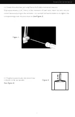
Page 11: ...male connector into the terminal connector at the rear speaker See Figure K Strip approximately 3 16 5mm of the insulation off each wire Insert the wire into the correct square opening on the connector Use a small flat head screwdriver to tighten the corresponding screw to secure the wire See Figure J Figure K Figure J 9 ...

Page 12: ...Through Connection From Power Amplifier To Next Speaker From Power Amplifier To Next Speaker Parallel Connection Figure L Figure M 13 Determine the proper wattage setting for each speaker in the installation and set each speaker s transformer tap selector on the front of the speaker accordingly See Figure N 14 Fit the grille onto the speaker See Figure O Figure N Figure O 10 ...

Page 13: ...Professional Collection Manual NOTES ...

Page 14: ...problem increases when a cable is being moved then the cable is most likely faulty or not connected properly Poor Sound Quality Today s audio systems may have several places to adjust the volume for example your MP3 player may have a volume control and your amplifier may also have one Check to be certain that the volume isn t turned up past 80 on any device Poor Sound Quality Try changing sources ...

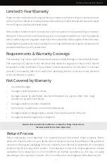
Page 15: ...d if the identifying number or serial number has been removed defaced or altered Requirements Warranty Coverage All warranties and warranty conditions are subject to change Please refer to the dealer portal for the latest information 13 Accidental damage Damage caused by abuse or misuse Damage caused by attempted repairs modifications by anyone other than Origin Acoustics or an authorized dealer D...

Page 16: ...75 S Decatur Blvd Las Vegas NV 89118 www originacoustics com 844 674 4461 2019 Origin Acoustics All copyrighted trademarked and patented elements mentioned herein are the sole property of Origin Acoustics ...

Reviews: