Page 2
I N T R O D U C T I O N
Read Carefully
- Congratulations and thankyour for
choosing an Origin Live turntable. You now have one of the
finest sounding turntables available – not only will it provide
an extraordinary level of performance but also reliability and
low maintenance. These instructions cover all decks listed on
the front cover, so photos and diagrams are for illustration
only. Specific instructions for a particular deck are always
included.
Critical performance factors
should be noted as follows:
Adjustable feet to be clear of plinth
Belt tension as it affects speed
Arm fastening tightness (read carefully as it depends on the
arm)
The portions of the instructions printed in
grey
are optional
reading that provide additional information if required. It is
critical that the remainder of the instructions are read fully
to achieve full potential performance. Underlined text is
especially important.
Although the instructions are written for owners with no
previous experience of turntables, there are aspects of the deck
that run contrary to expections, so experts should note that
before altering anything it is important to have fully read the
manual or degradation will result.
An Origin Live turntable is simple to set up. If you have a
problem, please refer to the instructions - failing this, you
should speak to your dealer or refer to technical support
on the Origin Live web site
- See top
navigation bar “dealers & information” then “technical
support” from the drop down list.
The deck can take approximately 20 minutes to set up
depending on your expertise. It can then be played and
later on the speed can finally be set with absolute accuracy.
As explained later this is because the electronics initially
experience speed drift (if they have not been run in) and may
need at least a day to run in properly.
We wish you an enjoyable time with your Origin Live
turntable.
P A R T S L I S T
Check that all parts are present.
Plinth & Sub-chassis
- including 1 cable clip
with nut & bolt.
Turntable bags
o
Threaded VTA adjuster
o
Cork washer for arm
o
4mm thick spacer for 3 point mounting
on Aurora & Calypso only
o
Oil bottle
o
screwdriver
o
2.5mm allen key for arm clip
o
2 p 1 steel foot (Sovereign only)
Platter & spindle (+ mat for Sovereign only)
(Sovereign only) Sub-platter & sub-platter mat
1 Belt
Motor pod
Standard or
upgrade transformer for 230 volt
or 110 volt mains supply
Arm (optional)
Turntable instructions & Strobe card
A V O I D S C R A T C H I N G T H E
H I G H G R A D E F I N I S H
To clean the surface use a soft lint free cloth
such as a duster – do not use tissue paper or
kitchen towel as these are mildly abrasive.
P R E P A R A T O R Y N O T E S
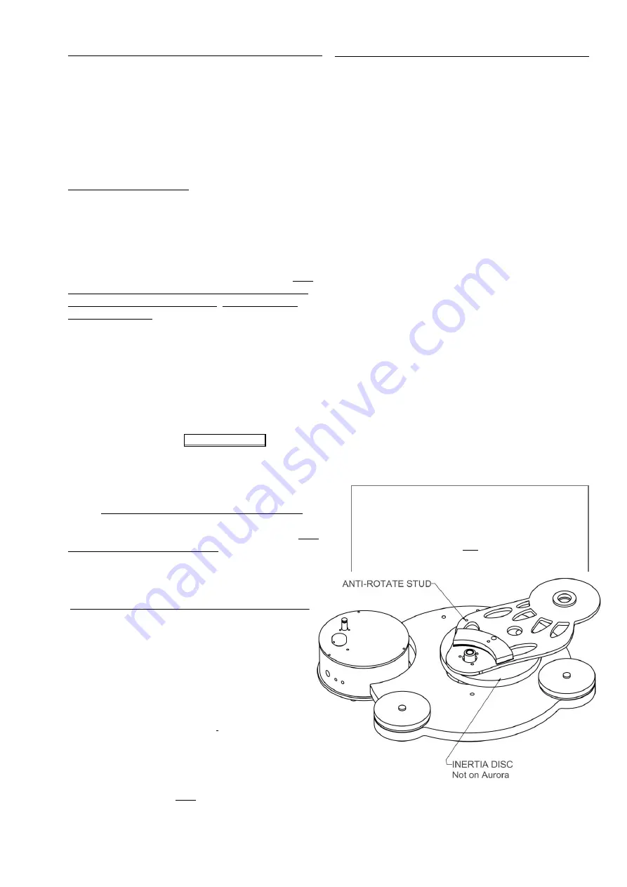
Your pre-assembled deck is illustrated in the adjacent
diagram. It is not necessary or advisable to dismantle the
deck.
You might make the mistake of thinking that the sub-
chassis is loose but in fact it is designed with freedom to
rotate very slightly from side to side but not “rock” up and
down much.
AURORA & SOVEREIGN ONLY - Note the anti-rotate
stud is replaced by a bolt which is factory fitted to the sub-
chassis. This should not be tampered with – it does not
bolt to the plinth as it’s only function is to stop the sub-
chassis rotating.
ALL OTHER DECKS - Note “the anti-rotate studs”
protrude either side of the inertia disc and locate in the
sub-chassis and plinth to prevent rotation.
DECK PRIOR TO INSERTING PLATTER


