background image

16


16


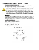
Operating Instructions


Moving the Arm Horizontally and Vertically 


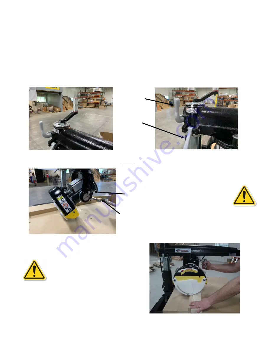
The elevating crank is used to raise or lower the arm to accommodate cutting operations (see below left).  Do not adjust the 

height of the saw with the base / clamp handle tight (see page 9 for location) or while the motor is running.  Change the posi-

tion of the arm for miter cutting is done by pulling the arm clamp handle (A) forward and lifting the miter latch handle (B).  

Observing the miter scale, swing the arm either right or left to the desired angle.  The arm can quickly be located at  the 0

o

 and 

45

o

 marks by using the indexing slots machined into the column ring.  When you have located the saw at the required position 

engage both the miter latch and the arm clamp.


!!! CAUTION !!! 

BOTH UPPER AND LOWER GUARDS MUST REMAIN IN PLACE FOR SAFE CUTTING OPERATION

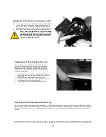
Rotating the Motor to Bevel Cutting 
Position 


Raise the arm to allow the saw blade sufficient clear-

ance above the table top.  Release the bevel clamp 

handle (A) and pull the bevel index pin. (B)  The motor 

can now be moved to a bevel position as indicated on 

the bevel scale.  Un

-

Lock the motor by releasing the 

bevel index pin (possible only at 0

o

, 45

o

 and 90

o

) and by 

locking the bevel clamp handle.


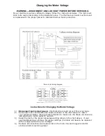
Cross Cutting  


Lock the arm in the 0

o

 position.  Place the material 

securely against the guide strip–


keep hands well away 

from the blade.  Draw the saw blade across the materi-

al.  After the cut has been completed return the blade 

behind the guide strip.  Observe this order of operation 

for all cross cuts.  Never push the saw blade into the 

material.  Pull the blade slowly and firmly across the 

material from the rear of the arm using the operating 

handle.  The saw blade should cut into the table about 

1/16” 

when cutting through the material.  Raise the 

anti

-

kickback to just clear the material being cut.  

Adjust for varying wood thickness or warped material.


A


B


A


B


Summary of Contents for 3531-01

Page 1: ...ANUAL PRIOR TO USING THE SAW REVIEW ALL SAFETY RULES AND OPERATING INSTRUCTIONS FREQUENTLY RADIAL ARM SAW TYPE 5 cross cut only 14 models 3531 01 3536 01 3531 03 3536 03 16 models 3541 3546 For Serial...

Page 2: ...the unlikely event there is trouble with your machine the Original Saw Company warrants the machine for the period of one year from the date of purchase The warranty covers defects in materials and w...

Page 3: ...3 3 Service Record Serial Number_____________________ Date Purchased ______________ Date Service Performed By...

Page 4: ...footwear is recommended when working outdoors 9 USE PROTECTIVE GLASSES If operation is dusty also wear a dust mask 10 DON T OVER REACH Keep proper balance and footing at all times 11 MAINTAIN TOOLS W...

Page 5: ...y devices certain residual risks cannot be avoided These are Impairment of hearing Risk of accidents caused by contact with the uncovered parts of the rotating saw blade Risk of injury when changing t...

Page 6: ...l or paint thinner to remove any residual wood pitch buildup Note do not lubricate the tracks Wipe down the bearings with denatured alcohol or paint thinner to remove any residual wood pitch buildup C...

Page 7: ...8 for replacement parts 6 Denotes hearing and eye protection required 7 Denotes guards required to be in place 8 Denotes general safety hazard See operators manual for more information pertaining to t...

Page 8: ...Arm General Caution Frame 4 Denotes lift point Note there are 2 on front of frame and 2 on the rear of the frame 1 Denotes read manual before using Arm left side 3 Denotes a pinch point on front of be...

Page 9: ...Elevating Control Handle D Miter Scale E On Off Switch F Adjustable Arm Stop G Operating Handle H Bevel Index Pin I Bevel Scale J Bevel Clamp Handle K Serial Number Plate L Carriage lock clamp M Carr...

Page 10: ...600 16 400 24 600 16 400 24 600 Max Miter cut capacity at 45o in 25mm stock Inches mm 10 875 276 15 5 393 10 875 276 15 5 393 10 875 276 15 5 393 Max crosscut width Inches mm 16 400 24 600 16 400 24...

Page 11: ...11 11...

Page 12: ...here it is to be set up then tighten legs this will allow machine to level itself to the floor Note if you are mounting our roller tables to the machine leave legs loose so assist in aligning the brac...

Page 13: ...as shown in the diagram on the inside of the starter box cover This is also found on pages 23 24 of this manual 3 Replace or adjust the thermal overload protectors D using dial A see below right with...

Page 14: ...e lower blade guard s effectiveness is limited in bevel operations It may have to be raised out of the way when set ting the bevel angle Be sure the power is off locked out and blade is completely sto...

Page 15: ...r arbor end bell with the guard stud through the hole in the guard Secure with wing nut 5 Reconnect the lower right guard and replace the parts removed 6 Move the carriage forward across the fence to...

Page 16: ...Motor to Bevel Cutting Position Raise the arm to allow the saw blade sufficient clear ance above the table top Release the bevel clamp handle A and pull the bevel index pin B The motor can now be move...

Page 17: ...n feed side almost touches the material Lower anti kickback assembly so the fingers are approximately 1 8 lower than the material Place material against the guide strip and feed evenly into the saw bl...

Page 18: ...dge of the guard closer to the material being cut Figure 3 Using the thumb screw adjust down the material hold down roller to contact the surface of the material being ripped Red arrows in Figure 4 Th...

Page 19: ...ssure clearance between blade and base Pull the blade through as you would for cross cutting Adjusting the tension on the auto carriage return spring Upon original setup of your Original saw you may w...

Page 20: ...b lightly then snug up the locknut 4 If the saw is equipped with a column clamp handle the adjustment should be made so that the clamp firmly secures the post when pushed back and re leased when the h...

Page 21: ...e machine has been exposed to the weather or used for a period of time the wood parts may become warped or worn so that the fence board is no longer straight It should be made straight by planing and...

Page 22: ...follow in the kerf of the front of the blade Signs of a blade heeling are indicated when the rear teeth of the blade mark the material with an offset in the cut This may be checked by cutting a piece...

Page 23: ...6th turn and screw in the same amount the set screw located on the bottom of the yoke trunion 4 Tighten the lock nuts engage the bevel clamp handle and recheck B If marks are made on the upper side of...

Page 24: ...e If your overload block does not have the proper settings the block will have to be replaced with one appropriate for your voltage 4 Recheck all connections and replace lids on the motor box and magn...

Page 25: ...ING If your machine requires a different voltage follow the instructions below The motor will need to be rewired according to the diagrams below The thermal overloads must be reset or replaced with th...

Page 26: ...loughing Fence not straight Feed rate too fast Wrong blade Column too loose in base Too much play between arm and column Rollerhead loose in arm Yoke loose when clamped to rollerhead Sawdust between l...

Page 27: ...se in arm Yoke too loose when clamped to rollerhead Bevel clamp handle loose Tabletop not parallel to arm Make proper adjustment p 20 Make proper adjustment p 18 Make proper adjustment p 18 Make prope...

Page 28: ...Low voltage voltage should be measured at the motor while it is starting and blade attached Voltage should not drop lower than 185 volts for 208 220 and 230 volt systems Check for loose or high resist...

Page 29: ...enuine replacement parts For parts or service please contact Original Saw for the dealer nearest you Printed in the USA The Original Saw Company 08 2019 HD Series Type 6 Updated electrical connections...

Reviews: