background image


52 

Version 4.2: Aug 26, 2015 


VI. 

CLEANING AND DECONTAMINATION 

Several procedures can be applied for decontaminating the workstation. Which procedure to select will depend on: 


The potential risk imminent in the agents used. 


The degree of purity required by an experiment or by work process. 

a.  Decontamination procedure: 

The following procedures can be applied for decontaminating the workstation. 

Wipe/spray disinfection: is the standard disinfection procedure for the MARS workstation. 

UV disinfection: If the unit is provided with a UV light, it is suited as an intensifying additional disinfection after the 
wipe/spray disinfection. 


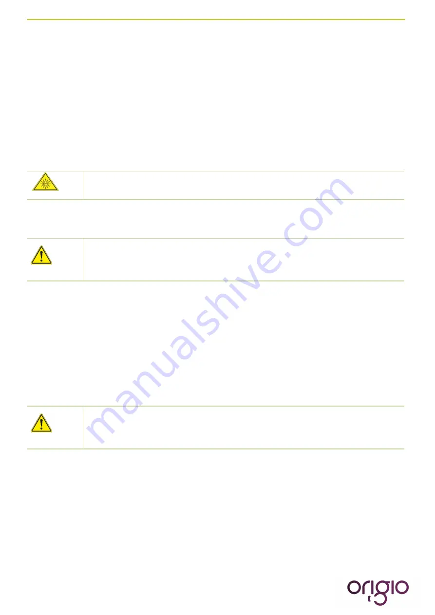
UV light may alter coloration of plastic components after extended exposure. 


Recommended disinfectants: Disinfectants based on quaternary ammonium compounds are acceptable for use 
and compatible with all components. 


Chloride-containing disinfectants may damage some surfaces. Therefore, use only 
disinfectants that do not contain chloride. 
 
Disinfectants with an alcohol content of more than 70% may alter plastic components 
after extended exposure. It also releases VOC’s which might affect samples. 


b.  Wipe/spray disinfection 

The Wipe / spray disinfection is to be performed at the following stages: 


Pre-disinfection 


Cleaning 


Final disinfection  


Pre-disinfection:  

1.  Switch ON the workstation. 


In a MARS IVF workstation, make sure that the microscope parts that are located 
outside the workstation are not obstructing the front window of the front. Remove 
or rotate towards the inside of the workstation the microscope’s eyepieces or eye 
tubes obstructing the front window   


2.  Move the front window to the cleaning position mode (refer to Section  VI, paragraph h. Front Window) 

3.  Remove all samples from the sample chamber and store them properly. 

4.  Remove accessories from the workstation and disinfect them using the disinfection procedure 

recommended by the manufacturer. 

5.  The stainless steel components of the work plate can be removed from the sample chamber and 

disinfected separately.   

6.  For pre-disinfection, spray disinfectant on all sample chamber surfaces or wipe the surfaces using 

disinfectant. 

7.  Do not remove the optional UV lamp from its base; wipe it thoroughly using a damp cloth. 

Summary of Contents for MARS 1200 CLASS II

Page 1: ...Mars Workstation User Manual...

Page 2: ...Version 4 2 Aug 26 2015...

Page 3: ...anual is meant to provide you with instruction on how to use the MARS workstation safely and effectively The MARS workstation provides you with unique features that will enable you to perform your IVF...

Page 4: ...LLATION 16 a Ambient Locations 16 Location requirements 16 b Room Ventilation 17 c Installation test 17 h Accessories 17 Light source TLB 7000 18 Heated Glass HG37 18 Humidifier 19 LED LCD Monitor 20...

Page 5: ...uto start Weekly or Daily 44 Option selected TODAY 45 Option selected AUTO 45 VII Setting up The timer function to control heating light source TLB7000 and Heated glass HG37 47 VIII Display Mode Funct...

Page 6: ...ARS 900 IVF or LAF 64 b MARS 1200 IVF or LAF 65 c MARS 1500 IVF or LAF 66 d MARS 1800 IVF or LAF 67 e MARS 1800 Dual 68 f MARS 1800MP 69 XII MAINTENANCE 70 a Field Certification 70 b Service 70 HEPA F...

Page 7: ...cident Should you encounter problems that are not properly detailed adequately in these operating instructions please contact ORIGIO immediately for your own safety If this manual is translated into o...

Page 8: ...II biological safety cabinet type A1 for installation and operation in IVF laboratories of biosafety levels 1 2 and 3 as described in Biosafety in Microbiological and Biomedical laboratories The refe...

Page 9: ...are WARNINGS CAUTIONS and IMPORTANT NOTES and they are used as follows NOTE Used to direct attention to a special item or for useful information WARNING DANGER UV light radiation hazard Use only with...

Page 10: ...icular purpose other than the one specified in ORIGIO literature that accompanies every specific product ORIGIO reserves the right to change or discontinue this product without prior notice Liability...

Page 11: ...oves Eye protection and face shields can also be worn as needed Special attention should be given to hands and lower parts of the arms as these are the parts of the operator most likely to emit partic...

Page 12: ...equire connection to a dedicated external exhaust through a thimble connection The HEPA filter is fragile and should not be touched Avoid puncturing either HEPA filter during installation or normal us...

Page 13: ...ons Caution High voltage Possibility of electric shock DANGER UV light radiation hazard Protect eyes and skin from exposure to UV light Protective Earth Symbol Label indicating lifting points to lift...

Page 14: ...one glass bottle per humidifier An integrated 21 monitor A USB connection A shelf for mounting for the Heated Glass All models Device documentation User manual Factory test report Cleaning and repair...

Page 15: ...at the device has been properly handled anti chock and anti tilt sensors are placed on the exterior of the crate In case of activation of the sensors please notify and report it immediately to your tr...

Page 16: ...ed must be of adequately height The distance between the exhaust air opening and the room ceiling must be at least 200 mm 8 in o The location must be equipped with an appropriate ventilation system o...

Page 17: ...e than 10 cm 4 9 inch The operator must request a written test report from the authorized test service Safety warranty The operational safety of the device particularly the samples is guaranteed only...

Page 18: ...rce TLB 7000 can be attached to the bottom of the workstation table plate To operate the light source please refer to the TLB 7000 Manual included in the provided instruction manual folder Heated Glas...

Page 19: ...0 5bar 5 Fill the humidifier glass 4 5 up with distilled water The water will only need to be replaced occasionally Do not use 100 CO2 this will be lethal to your samples Use only premixed 5 or 6 CO2...

Page 20: ...not provided to pull the monitor out of the back wall 4 Place delicately the monitor on the table plate that has been covered to avoid scratches Adjust the contrast or brilliance of the monitor Place...

Page 21: ...Version 4 2 Aug 26 2015 21...

Page 22: ...22 Version 4 2 Aug 26 2015...

Page 23: ...Version 4 2 Aug 26 2015 23...

Page 24: ...24 Version 4 2 Aug 26 2015...

Page 25: ...d in the MARS IVF workstation The stereomicroscope can be fitted with an analogue or digital camera Note Microscope and camera models and brands vary greatly The below installation is given as an exam...

Page 26: ...bles remove the frame around the monitor by unscrewing the screws Remove the frame and the cover glass Use a window suction tool not provided to pull the monitor out of the back wall Place delicately...

Page 27: ...erformed by a certificated or technically trained engineer approved by ORIGIO or our authorized distribution network To Operate the Liquid Bath controller please refer to the provided instruction manu...

Page 28: ...ARS IVF CLASS II 1800D MARS IVF CLASS II 1800MP The MARS workstation has a built in microprocessor controller featuring LCD display indicating fan and alarm status Air velocity sensors Clock 7 days an...

Page 29: ...indow 6 Laminated safety Glass front window 7 Electrical outlets 8 Cable channel integrated in the support frame 9 Legs 10 Stainless steel table plate 11 Support frame 12 Feet adjustable 13 VOC Filter...

Page 30: ...1 Stainless Steel Work plate 12 Heated Glass controller HG37 13 Integrated cable channel 14 Support frame 15 Stainless Steel Work plate 16 Heated surface 17 Light source 18 Heated Glass HG 37 19 Micro...

Page 31: ...Version 4 2 Aug 26 2015 31 b Inner overview MARS MODEL 1 Exhaust HEPA Filter 2 Fan s 3 Plenum 4 HEPA filter 5 Laminator air panel...

Page 32: ...e chamber work opening through the perforated wholes in the table top A The air is drawn through the air plenum under the work surface through the floor pan and behind the rear interior wall B The roo...

Page 33: ...ainless steel work plates A B C D placed onto the frame above the sample chamber floor pan For cleaning of the floor pan the work plates A B C D can be lifted with the handles mounted in the grille Th...

Page 34: ...accessories e g a microscope From a cleaning mode C in which the front window 2 is completely opened the Sample chamber of the MARS is accessible by pressing constantly on the arrow on the control pa...

Page 35: ...the 1 Fan Velocity Button to turn the fans OFF When activated the small green light on top of the button will be OFF To prevent any accidental switching ON or OFF of the fan the buttons for normal an...

Page 36: ...e illumination light of the work chamber press the 4 Internal Light button When activated a small blue light on top of the button will switch on To switch OFF the illumination light of the work chambe...

Page 37: ...F To switch OFF the ORIGIO Light Source and the working heated surface s press the button again The small blue light on top of the button will be switched OFF B CONTROL PROGRAMMING This section descri...

Page 38: ...the configuration of the workstation there can be up to two fans designated FLOW 1 FLOW 2 To learn how to enable and disable these functions refer to the section Programming the Air Flow to Auto Start...

Page 39: ...nter button to enter the menu The USER MODE with the LIGHT LEVEL will be displayed together with a representation of the Control Programming Keys The first line with the arrow symbol enables the user...

Page 40: ...ter button to enter the menu Press on the right arrow button to enter the next menu The USER MODE with the UV CONTROL will be displayed together with a representation of the Control Programming Keys T...

Page 41: ...RT and OFF TIME 00 00 will be displayed This is the Time at which the UV Light will switch off Press the enter button to validate your choice The first digit of the hour will be blinking To enter the...

Page 42: ...hour will be blinking To enter the hour press the appropriate number found on the control panel Continue this operation for the hours and the minutes This will indicate the time when the UV light wil...

Page 43: ...Press on the DOWN or UP arrows to change the settings from 12H to 24H and vice versa Press the enter button to enter the menu The SET WATCH menu with TIME will be displayed The first digit of the hou...

Page 44: ...nable and program the airflow to auto start on a specific date and time and how to disable that feature Press the enter button to enter the menu Press on the RIGHT or LEFT arrow button to reach the me...

Page 45: ...s the enter button to validate your choices The FAN AUTOSTART and OFF TIME 00 00 will be displayed This is the time at which the fans will turn off Press the enter button to enter the menu The first d...

Page 46: ...will be blinking To enter the hour press the appropriate number found on the control panel Continue this operation for the hours and the minutes This will indicate the time when the fan will turn OFF...

Page 47: ...l and press enter Press on the RIGHT or LEFT arrow button to navigate towards the information menu until you reach the EXT CONTROL menu Press Enter to reach the display OUT 1 Go into OUT1 by pressing...

Page 48: ...king To enter the hour press the appropriate number found on the control panel Continue this operation for the hours and the minutes This will indicate the end time Press the enter button to validate...

Page 49: ...AY MODE will be displayed together with a representation of the Control Programming Keys Press the enter button to enter the menu The DISPLAY MODE and FLOW ON will be displayed together with a represe...

Page 50: ...the menu Press on the DOWN or UP arrow to reach the following display The DISPLAY MODE and TIME OUT 005 SEC will be displayed This feature indicates that any information or changes will remain displa...

Page 51: ...e defined work area of the work plate Do not place unnecessary items into the sample chamber Use only disinfected and cleaned accessories for the work process Do not cause air turbulence by quick hand...

Page 52: ...f more than 70 may alter plastic components after extended exposure It also releases VOC s which might affect samples b Wipe spray disinfection The Wipe spray disinfection is to be performed at the fo...

Page 53: ...recommended to be taken after the wipe spray disinfection The UV disinfection can be performed by using the optional integrated UV lamps in the MARS The run time of the routine can be preset from the...

Page 54: ...ximately 30l h and leave the flow running for 20 minutes Turn the gas flow off Disconnect the tubes and empty the remains of the bottle and rinse the bottle and diffuser extensively with water Empty t...

Page 55: ...ht button again The small yellow light on top of the button will be OFF To switch OFF the ORIGIO Light Source and the working heated surface s press the 6 key button again The small light on top of th...

Page 56: ...OMMISSIONING Warning When the workstation has to be decommissioned the process of decontamination and discard has to be followed according to national rules and regulations applicable in the country w...

Page 57: ...e back of the work table Then follow the instructions From STANDARD DISPLAY Press on the RIGHT or LEFT arrow button to navigate towards the information menu until you reach the SERVICE MODE Press on t...

Page 58: ...on the ENTER button FLOW ALARM 1 with LOW and a set of values will be displayed e g 0175 Press on the arrow up until the alarms starts By pushing the arrow the numbers will decrease by units By maint...

Page 59: ...ump please refer to the user manual of the water circulator pump not included in this manual The heated area is indicated by a brushed steel effect in the work surface Operational Characteristics The...

Page 60: ...ut from the chosen channel only channel 1 is used in this example In case of an alarm situation a red light will start flashing in the top left hand corner of the display On the right hand side of the...

Page 61: ...ced below the display These are described in the figure above Each button has two functions one in each side of the button Simply press the appropriate symbol to use the buttons The heated surface is...

Page 62: ...menu Press and release the information button To the select the data to be displayed press the UP or DOWN arrow Press the information button to display the value you have selected Resetting the THI an...

Page 63: ...ect the settings from intentional or unintentional changes Press the information button to enter the INFO menu Use the UP and DOWN arrows to select LOC keypad lock Set the parameter LOC YES to lock th...

Page 64: ...H 14 size Power consumption 125 W Power consumption normal operation LAF 270 W IVF 660 W heat plate warm up Max power consumption outlets total 400 W Main overcurrent protection fuses Workstation Rati...

Page 65: ...nsumption normal operation LAF 290 W IVF 680 W heat plate warm up Max power consumption outlets total 400 W Main overcurrent protection fuses Workstation Rating LAF IVF 230V 3 15 A 6 3 A 115 V 6 3 A 8...

Page 66: ...nsumption normal operation LAF 375 W IVF 765 W heat plate warm up Max power consumption outlets total 400 W Main overcurrent protection fuses Workstation Rating LAF IVF 230V 3 15 A 6 3 A 115 V 6 3 A 8...

Page 67: ...nsumption normal operation LAF 415 W IVF 805 W heat plate warm up Max power consumption outlets total 400 W Main overcurrent protection fuses Workstation Rating LAF IVF 230V 3 15 A 6 3 A 115 V 6 3 A 8...

Page 68: ...ion normal operation 1147 W heat plate warm up Max power consumption outlets total 400 W Main overcurrent protection fuses Workstation Rating LAF IVF 230V NA 6 3 A 115 V NA 12 A Outlet overcurrent pro...

Page 69: ...plate warm up Max power consumption outlets total 400 W Main overcurrent protection fuses Workstation Rating LAF IVF 230V NA 6 3 A 115 V NA 8 A Outlet overcurrent protection fuse Workstation Rating LA...

Page 70: ...ormed Sample chamber illumination tube To access or exchange the light tube the laminator air panel must first be removed 1 To access the laminator air panel it is first necessary to remove the micros...

Page 71: ...s WARNING The radiation of the HNS lamps causes skin burns and conjunctivitis within minutes For this reasons skin and eyes must be protected from direct radiation Retrofitting and repairs WARNING All...

Page 72: ...t and top of the workstation to remove any accumulated dust Clean and disinfect the humidification device All weekly activities Please refer to the Cleaning and decontamination section of this manual...

Page 73: ...n of the certification provider comfort and safety tests lighting intensity noise level vibration electrical leakage ground circuit resistance and polarity tests Particle count VOC count Temperature c...

Page 74: ...06 Light tube 26 1200 mm length for FORTUNA and MARS 1500 WG0507 Light tube 26 1500 mm length for FORTUNA and MARS 1800 WG0777 Light Ballast FORTUNA and MARS 900 and 1200 WG0778 Light Ballast FORTUNA...

Page 75: ...Version 4 2 Aug 26 2015 75 ORIGIO a s Knardrupvej 2 2760 M l v Denmark Tel 45 46 79 02 00 Fax 45 46 79 03 00 Customer service origio com www origio com...

Reviews: