


IDS-141A_181A Series
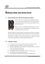
User’s Manual
13
ORing Industrial Networking Corp.
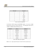
Pin Number
Assignment
1
TD+
2
TD-
3
RD+
4
Not used
5
Not used
6
RD-
7
Not used
8
Not used
Table 4-2 RJ-45 Pin Assignments
The IDS-141A / IDS-181A supports auto MDI/MDI-X operation. You can use a straight-
through cable to connect PC to IDS-141A / IDS-181A. The following table below shows the
10BASE-T/ 100BASE-TX MDI and MDI-X port pin outs.
Pin Number
MDI port
MDI-X port
1
TD+(transmit)
RD+(receive)
2
TD-(transmit)
RD-(receive)
3
RD+(receive)
TD+(transmit)
4
Not used
Not used
5
Not used
Not used
6
RD-(receive)
TD-(transmit)
7
Not used
Not used
8
Not used
Not used
Table 4-2 MDI / MDI-X pins assignment
Note:
“+” and “-” signs represent the polarity of the wires that make up each wire pair.
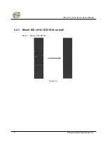
Summary of Contents for IDS-141A
Page 4: ......


