


IDS-141A_181A Series
User’s Manual
ORing Industrial Networking Corp
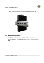
8.
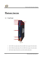
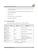
4. LED for Serial ports status. When data transmitted, the green LED will be light on. (S5~S8
only available for IDS-181A)
5. LED for Serial ports status. When data transmitted, the green LED will be light on. (S5~S8
only available for IDS-181A)
6.
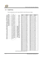
DB62 Female
port.
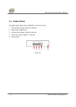
7. Reset button, press for 10 sec for factory default.
8. 10/100Base-T(X) Ethernet port
3.2 Front Panel LEDS
The following table describes the labels that stick on the IDS-141A / IDS-181A.
LED
Color
Status
Description
PWR1
Green
On
DC power 1 activated.
Blinking
System Booting / Located by administrator
PWR2
Green
On
DC power 2 activated.
Blinking
System Booting / Located by administrator
Fault
Amber
On
Fault event occurred.
S1 ~ S8
Green
Blinking
Serial port is transmitting/receiving
data
(S5~S8 only available for IDS-181A)
ETH
Green/Amber
Green/Amber On/Blinking 100Mbps LNK/ACT
Green On/Blinking
10Mbps LNK/ACT
Table 3-1 Front panel LEDs
Summary of Contents for IDS-141A
Page 4: ......


